JX-350_EPU使用说明书.pdf - 第54页
EPU Instruction M anual C hapter 4 Creating a Production Progr am 4-6 (3) Scal e type For mark ( BOC mark and area mark ) recog nition f or the whole PW B, t he following 2 methods are selectable. Selection should be mad…
EPU Instruction Manual Chapter 4 Creating a Production Program
4-5
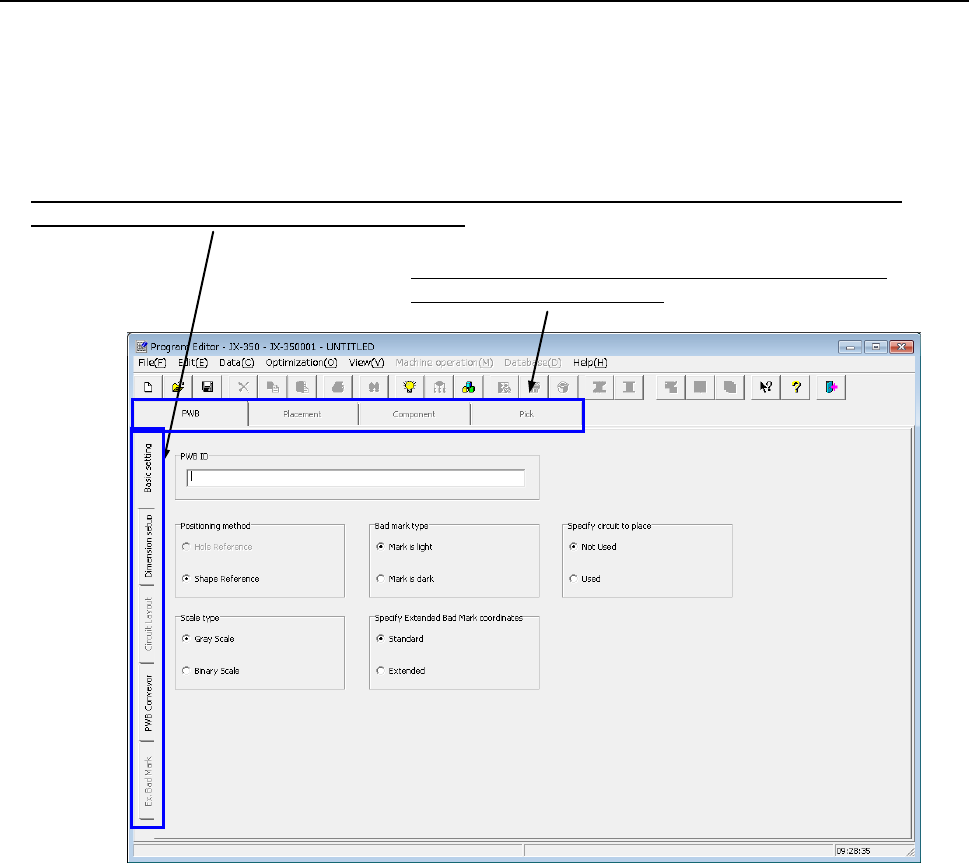
4.1.2.1 Basic setting
There are six items on the “Basic setting” tab.
Enter or select data according to the PWB to be produced.
After program editing is started or after "New" is selected in the file menu, the program
name is changed into UNTITLED.
Switch the screen: “Basic setting,” “Dimension setup,” “Circuit layout,” “PWB Conveyor” or “Ex. Bad Mark”.
(Select the “tab” corresponding to the desired screen.)
Switch the data screen among PWB data, Placement data,
Component data and Pick data.
Make the following settings (1) to (6) on the “PWB” data screen.
(1) PWB ID
Enter a “comment” that elaborates on the PWB name.
You can specify the PWB ID with up to 60 alphanumeric characters and/or symbols.
The PWB ID entered here is displayed on the screen while you are creating a
production program or while the system is producing a PWB. Therefore, enter the
PWB ID easy to recognize here.
You can omit the PWB ID.
(2) Positioning method
♦ Hole Reference: * Not used in JX-350.
♦ Shape Reference: This method positions a PWB by fixing its edges mechanically:
it does not use any positioning hole of a PWB.

EPU Instruction Manual Chapter 4 Creating a Production Program
4-6
(3) Scale type
For mark (BOC mark and area mark) recognition for the whole PWB, the following 2
methods are selectable.
Selection should be made according to the condition of the BOC mark.
♦ Gray Scale: A mark will be recognized using all information obtained by the
OCC camera. This method is available even in a high noise
environment because much information is used. Normally select
this option.
* If a certain level of coincidence is obtained though the external shape is partially
missing, the recognition result is regarded as OK.
♦ Binary Scale: If an error occur during the gray scale recognition, select binary
scale recognition. If the edge of the mark is not shot clearly, the
accuracy will be lower than that of the gray scale recognition
method.
(4) Bad mark type
A bad mark may be given to a multi-plane PWB so that a component will not be
placed on a defective circuit (circuit that caused an error during the previous process).
If the OCC or a bad mark sensor (optional) detects a bad mark of each circuit before
PWB production, the system will skip a component on which the sensor detects a bad
mark to produce a PWB.
* For using the bad mark, it is necessary to adjust the bad mark reader at machine
setup before production.
♦ Mark is light: Select this option if the reflectance of the PWB is lower than that of
bad mark, for example, if a white bad mark is on a green PWB.
♦ Mark is dark: Select this option if the reflectance of the PWB is higher than that
of bad mark for example, if a black bad mark is on a ceramic PWB.
(5) Specify Extended Bad Mark coordinates
Specify a position from which the bad mark coordinates are viewed, the origin of a
circuit or that of a board. If you select the “Extend” radio button when you select the
“Used” radio button in the “Multi circuit references” column, the system automatically
specifies the coordinates viewed from the origin of the reference circuit.
♦ Standard: Select this radio button if you are to specify the coordinates of a bad
mark viewed from the origin of a circuit.
♦ Extended: Select this radio button if you are to specify the coordinates of a bad
mark viewed from the origin of a board.
Registration mark
Recognition mark

EPU Instruction Manual Chapter 4 Creating a Production Program
4-7
(6) Circuit Mapping
This menu item allows you to specify whether to use the function for specifying a
circuit to be placed on a board. When you produce a multi-circuit board and you
know which circuit(s) is (are) not to be placed on a board, you can set it (them) so
that it (they) will not be placed on a board.
♦ Not Used:
Select this radio button when you produce PWBs without specifying which circuit is
not placed on a multi-circuit board. Select this radio button when you produce a
single-plane PWB also.
♦ Used:
Select this radio button when you produce a multi-circuit PWB with specifying which
circuit is to be placed on a board.
* See Section 4.1.2.3 “Circuit Layout” for description of the function for specifying a
circuit to be placed on a board.
When you select the “Used” radio button for the menu item “Bad mark” and select
the “Used” radio button for the menu item “Circuit Mapping”, both functions are
enabled. The system does not recognize any bad mark of circuits whose “Skip”
item is set to “Yes” on the “Circuit Layout” tab.