JX-350_EPU使用说明书.pdf - 第129页
EPU Instruction M anual C hapter 4 Creating a Production Progr am 4- 81 ( 4) Component verificat ion * JX- 350 is not applicable to the com po nent verificat ion . ( 5) Di mension check S pecif y whether to check a dimen…
EPU Instruction Manual Chapter 4 Creating a Production Program
4-80
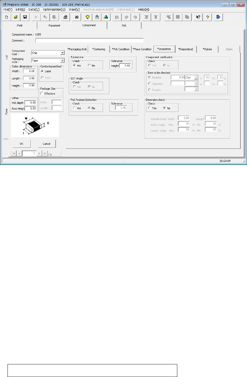
4.1.4.2.6 Inspection
Specify the fields “Tombstone,” “SOT Angle,” “Pick Position Detection,” “Component
verification,” and “Dimension check.”
The field “SOT Angle” is optional.
(1) Tombstone
Specify whether to check that a component stands on its side (“Tombstone” error).
Normally, we recommend that you select the “Yes” radio button for a 3216 chip
component or smaller ones. Therefore, when you select a “Chip” as the
“Component type,” the system automatically selects the “Yes” radio button.
“Tolerance”: The system automatically enters a value calculated from the component
height you entered to this field..
(2) SOT Angle (option)
This specifies whether to perform or not 3-terminal lead SOT direction inspection.
The SOT direction inspection of the first component before production and after “no
components” can be performed.
Perform this check mainly to check that a correct component is not set.
This function can be selected only when the component type is SOT.
(3) Pick Position Detection
This function detects whether the center of a component is shifted by a value more
than that set in the “Tolerance” field when viewed from the center of the nozzle.
This function is available only if the packaging style is a tape feeder. Otherwise, this
function is disabled. Select the “Yes” radio button for the desired component, and
enter the value in the “Tolerance” field as the judgment value.
The range of a value you can enter in this field is from 0 to the length of a component (or
width of a component if the component supply angle is 90º or 270º).
When you select the “Yes” radio button, the default value to be set in the “To lerance”
field is calculated with the expression shown below:
Length (or width) of a component ÷ 2 × (set value/100)
The “set value” is set in the “Environment setting” screen of the Program Editor. The
default is 50 (%).
EPU Instruction Manual Chapter 4 Creating a Production Program
4-81
(4) Component verification
* JX-350 is not applicable to the component verification.
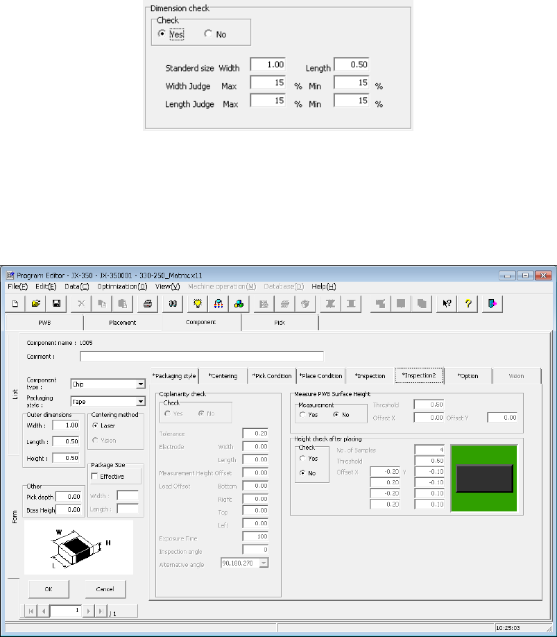
(5) Dimension check
Specify whether to check a dimension of a component, and enter the standard size
and the size used for judgment if the system checks.
If you check the “Yes” radio button in the “Check” field, the system checks the width
and length of a component when centered, and an error occurs if these dimensions
exceeds the upper/lower limits and the system judges that the component is
irregularly-shaped.
Use this check function mainly to check that a component of the specified size is not
set.
The system performs this check when it centers a component during production.
The component to be judged is laser centering component.
4.1.4.2.7 Inspection 2
On this tab, you can make settings of the coplanarity check data (“Coplanarity check”),
those of measurement of the board surface height on which a component is placed
(“Measure PWB Surface Height”) and those of measurement of the component height
after it is placed on a board (“Check Component Height after place”).
(1) Coplanarity inspection data
* JX-350 is not applicable to the coplanarity inspection data.
EPU Instruction Manual Chapter 4 Creating a Production Program
4-82
(2) Measure PWB Surface Height
This setting item allows the system to measure the height of the board surface at the
component placement position to correct the Z-coordinate of the component
placement position.
The center (one point) of the component placement position is to be measured.
According to the measurement result, enter the threshold value for determining
whether the board warps or not in the “Threshold” field.
When the measurement result is within the range of – “Threshold value” to “Threshold
value,” the system determines that a component can be placed on the board.
To measure a position other than the component placement position, enter the “Offset
X” and “Offset Y” fields.
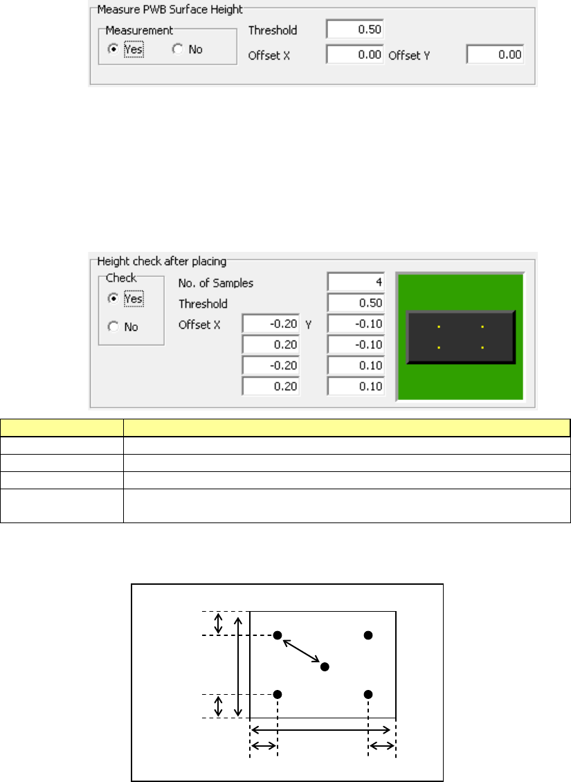
(3) Check Component Height after place
This setting item allows the system to measure the heights of four corners of a
component such as one having a boss after it is placed on a board, and check to see
if the placed component is tilted or not.
When the measurement result is within the range of – “Threshold value” to “Threshold
value,” the system determines that the component has been placed on the board
normally.
If it exceeds this range, the current production stops temporarily.
Setting item
Description
Check
Specify whether to check or not by selecting the corresponding radio button.
No. of Samples
Specify how many positions to be checked within the range of 2 to 4.
Threshold
Specify a value for determining whether a placed component is tilted or not.
Offset X, Y
Specify where to check by entering the offset from the component placement
position. From the top, specify the measurement positions 1, 2, 3 and 4.
The relation between the measurement offset positions and the check positions is
shown in the figure below.
Offset value
30% of the
vertical length
Measuring
position 1
Measuring
position 3
Measuring
position 2
Measuring
position 4
30% of the
horizontal length
30% of the
vertical length
30% of the
horizontal length