JX-350_EPU使用说明书.pdf - 第43页
EPU Instructi on Manual Chapter 3 E PU setup 3- 17 Option • This tab displays the units w hich can be installed on the station a s an option. Setting item Description Remarks B ad Mark R eader Check the “ Attach ” check …
EPU Instruction Manual Chapter 3 EPU setup
3-16
3.7.1.6 Setting the unit conditions
Set the unit conditions of your station.
Be sure to set the items displayed on this screen so that they are consistent with the
settings on the “Device enable” screen invoked from the Machine Setup menu of the main
unit. Refer to Chapter 7 “Machine Setup” of the “Instruction Manual CD.”
- The setting items to be set are displayed on two screens: “Standard” screen and
“Option” screen. Click the corresponding tab displayed at the left top corner.
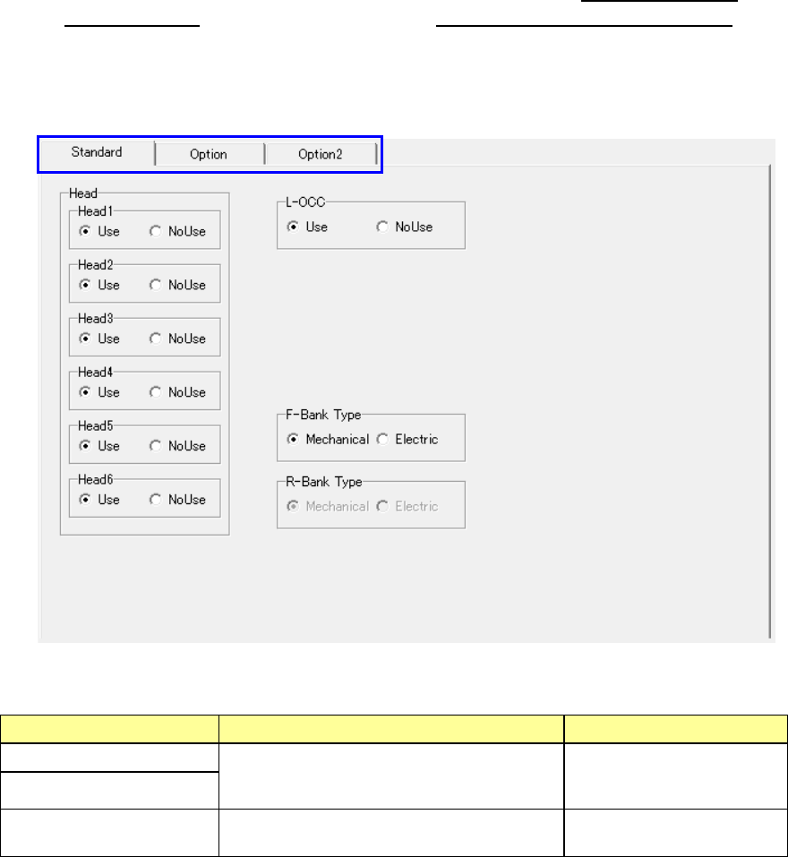
Standard items
• Display the units provided as the standard devices.
Setting item Description Remarks
Head 1 to 6
Select whether the unit is to be used or not
with checking either of the radio buttons
“Use” and “NoUse.”
L-OCC
F-Bank Type
R-Bank Type
Select a bank type using either the
“Mechanical” or “Electric” radio button.
* 1 You can change this setting item only when “Rear supply device” is set at “Use.”
EPU Instruction Manual Chapter 3 EPU setup
3-17
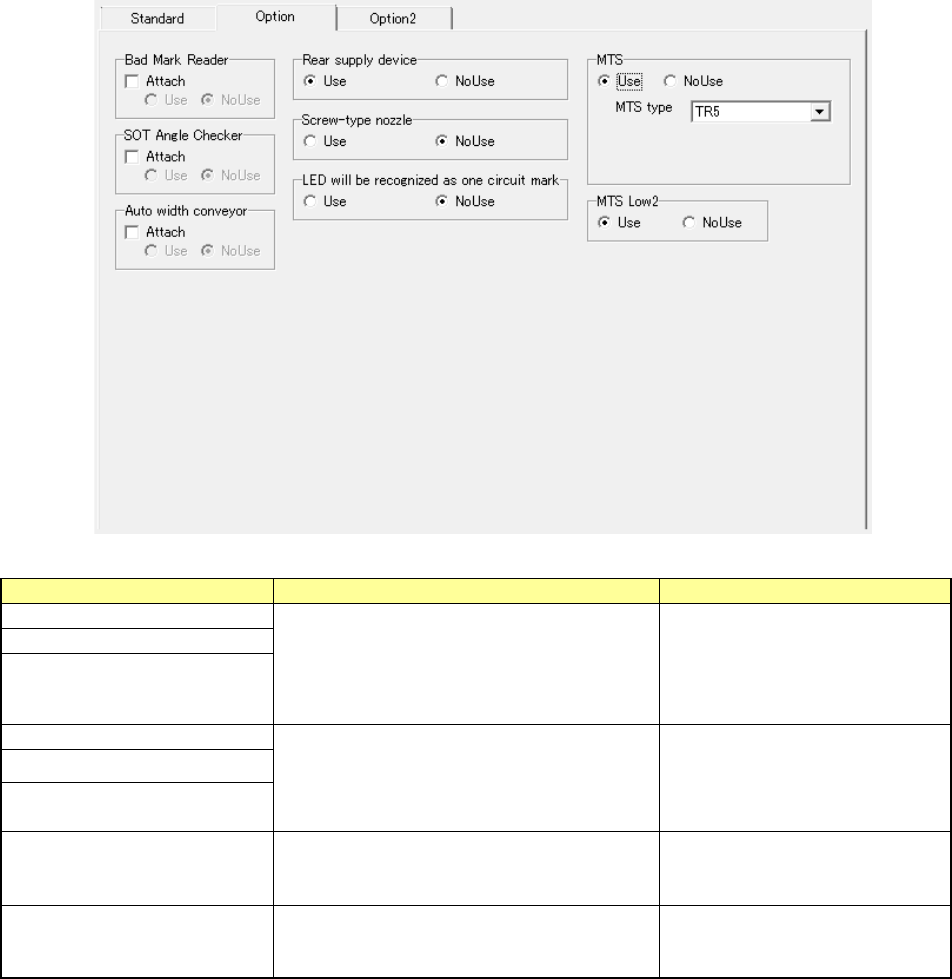
Option
• This tab displays the units which can be installed on the station as an option.
Setting item
Description
Remarks
Bad Mark Reader
Check the “Attach” check box if the unit is
attached on the system, and select either of
the radio buttons “Use” and “NoUse.”
When the “Attach” check box is
not checked, the “Use” and
“NoUse” radio buttons are
dimmed, and you cannot make
any settings.
SOT Angle Checker
Auto width conveyor
Rear supply device
Select either of the radio buttons “Use” and
“NoUse.”
“S-VCS” is displayed depending
on the model.
Screw-type nozzle
LED will be recognized as one
circuit mark
MTS (*1) (*2)
Select either of the radio buttons “Use” and
“NoUse.”Only “TR5” can be selected in the
“MTS type” field.
MTS Low2
Select either of the radio buttons “Use” and
“NoUse.”
Only when you use an “MTS,”
this setting item is displayed on
the screen.
* 1 You can change this setting item only when “Rear supply device” is set at “Use.”
* 2 When you select the “Electric” radio button for the setting item “R-Bank Type”
on the
[Standard] tab, each item is displayed in gray and you cannot set any of the items.
EPU Instruction Manual Chapter 3 EPU setup
3-18
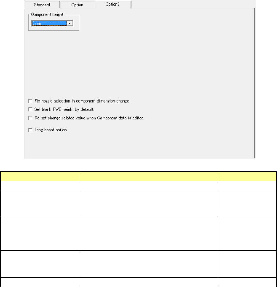
Option 2
• Display the units which can be installed as an option.
Setting item Description Remarks
Component height Select the component height. (6mm/12mm)
Fix nozzle selection in
component dimension
change.
When you check this check box, the system continues
using the nozzle already set without changing the nozzle
selection even though you change the dimensions of a
component on the “Component” data screen.
Set blank PWB height by
default.
Leave blank the “Thickness” field of a board on the
“PWB” data screen without setting the default value.
When you load a production program for a model having
no board thickness data to the system, this field
becomes blank also.
Do not change related value
when Component data is
edited.
When you check this check box, the system does not set
the standard value (initial value) to each item already set
except the edited item(s) even though you edit the
component data already set.
Long board option Select this item to use the long board option.