JX-350_EPU使用说明书.pdf - 第132页
EPU Instruction M anual C hapter 4 Creating a Production Progr am 4- 84 4.1.5 Pick data This “ Pick ” data screen allows you to specify where a component is supplied and where it is picked up. The component feed units pr…

EPU Instruction Manual Chapter 4 Creating a Production Program
4-83
* Regarding the data of the “Inspection” and “Inspection 2” tabs, the entry may be
restricted depending on setting such as the component type.
Component type Tombstone
Dimension
check
SOT
Angle
Pick
Position
Detection
Measure
PWB
Surface
Height
Check
Component
Height after
place
Square chip
○
○
×
○
○
○
Square chip (LED)
○
○
×
○
○
○
MELF
○
○
×
○
○
○
Aluminum electrolytic
capacitor
○ ○ × ○ ○ ○
SOT
○
○
○
○
○
○
Trimmer
○
○
×
○
○
○
Network resistor
○
○
×
○
○
○
SOP
○
○
×
○
○
○
HSOP
○
○
×
○
○
○
SOJ
○
○
×
○
○
○
QFP
○
○
×
○
○
○
GaAsFET
○
○
×
○
○
○
PLCC (QFJ)
○
○
×
○
○
○
PQFP (BQFP)
○
○
×
○
○
○
TSOP
○
○
×
○
○
○
TSOP2
○
○
×
○
○
○
BGA
○
○
×
○
○
○
QFN
○
○
×
○
○
○
Unidirectional lead
connector
○ ○ × ○ ○ ○
Bidirectional lead
connector
○ ○ × ○ ○ ○
Z-lead connector
○
○
×
○
○
○
J-lead socket
○
○
×
○
○
○
Gull-wing socket
○
○
×
○
○
○
Socket with bumper
○
○
×
○
○
○
Other components
○
○
×
○
○
○
4.1.4.2.8 Option
* JX-350 is not applicable to the opyion.
4.1.4.2.9 Vision data
* JX-350 is not applicable to the version data.
EPU Instruction Manual Chapter 4 Creating a Production Program
4-84
4.1.5 Pick data
This “Pick” data screen allows you to specify where a component is supplied and where it
is picked up.
The component feed units provided in the feeder bank are a tape feeder, stick feeder,
bulk feeder, and tray holder. The other component feed unit is MTS.
Additionally, there are two kinds of feeder banks, mechanical feeder bank and electric
feeder bank. The mechanical feeder bank uses the mechanical feeder while the electric
feeder bank uses the electric feeder.
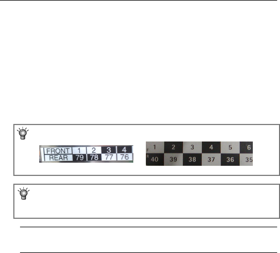
For the mechanical feeder bank, there are 79 holes in one feeder bank intended to set the
feeder. The number of a hole, into which the pin at the top end of the feeder is inserted,
becomes the feeder number assigned to the feeder.
For the electric feeder bank, there are 40 rails on one feeder bank.
The number of a rail, onto which the feeder is mounted, becomes the number assigned to
the pick data.
* In the feeder bank, numbers are expressed in 2 upper and lower rows.
On the front side, the upper-row numbers are those for feeder settings.
<Mechanical feeder bank> <Electric bank>
* The component pick-up position is automatically assigned with the Optimization
function, but you have to manually assign the pick-up position in the following cases
• when the feeder layout is fixed, or
• when you change the feeder layout after optimization.
Note: If you load a production program file created with another model, the system may
recalculate the component pick-up coordinates set as the Pick data mainly because
the reference coordinates vary depending on the model.
EPU Instruction Manual Chapter 4 Creating a Production Program
4-85
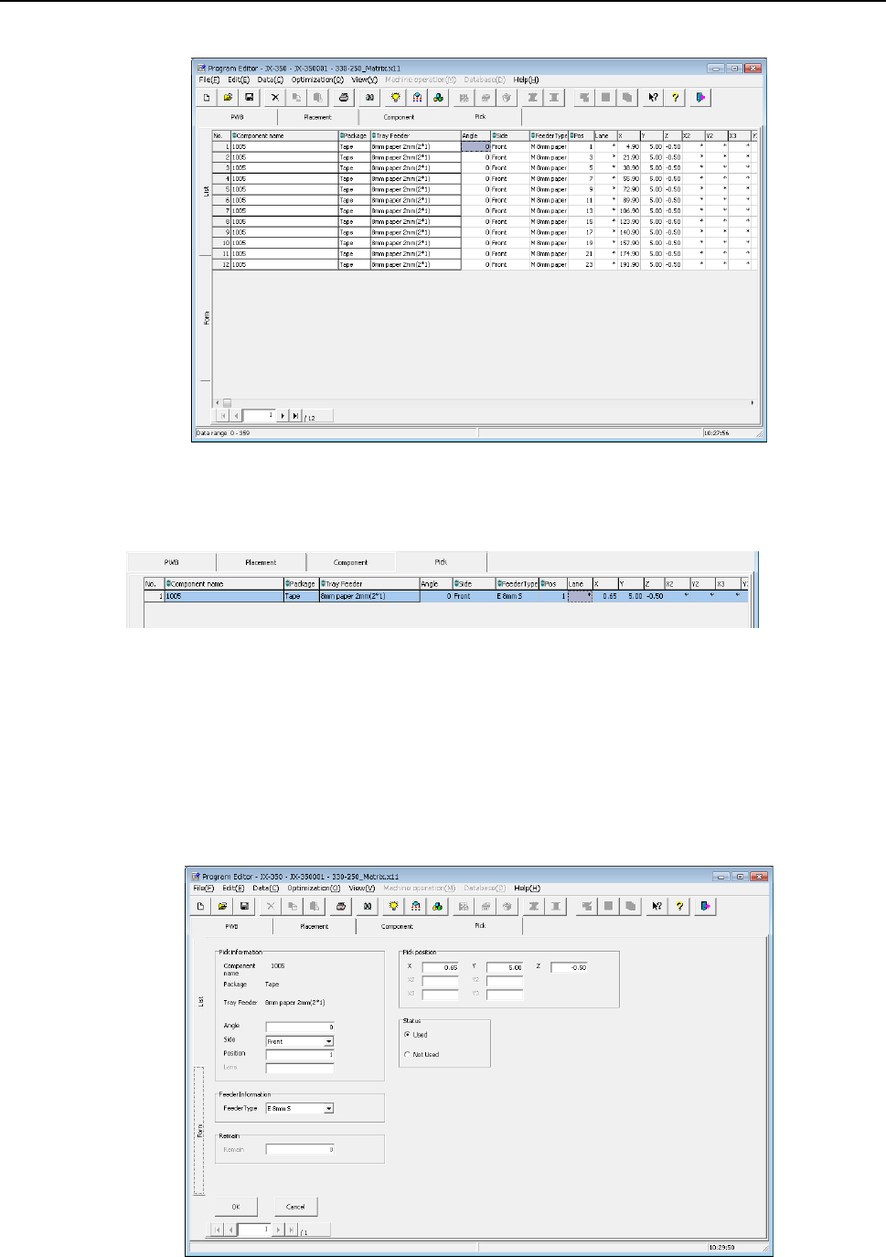
4.1.5.1 “Pick” data screen display
When you display the “Pick” data screen, the “List” screen opens at first.
When the electric-powered feeder is used, the following items are displayed in light blue
on the list screen.
When you select the “Form” tab on the “Component List” screen or double-click the
“Component List” screen, the “Component Form” screen appears showing the
corresponding data on the line where the focus is located.
Values you entered on the “Placement” and “Component” data screens are displayed in
the fields of “Component name,” “Package” and a feeder unit respectively.
You can edit the eight items, “Angle,” “Side,” “Position,” “Lane,” “Pick position”, “Status”,
“Feeder Type” and “Remain” on the “Form” screen.