JX-350_EPU使用说明书.pdf - 第107页
EPU Instruction M anual C hapter 4 Creating a Production Progr am 4- 59 (3) T ray input method 1) Pilot Position Enter the distance f rom t he tray outside to the center position (X, Y) of the f irst tray component. 2) P…
EPU Instruction Manual Chapter 4 Creating a Production Program
4-58
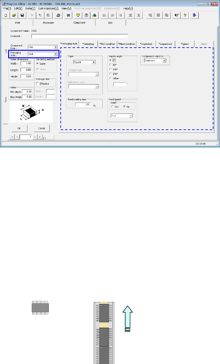
(2) How to enter data if you select “Stick” as the “Packaging style”
1) Type
Select a stick feeder type.
2) Feed waiting time
Set the ratio of the actual waiting time to the waiting time (that is, waiting time set
per feeder type) the system has to wait until it system can pick up the next
component after picking up the current component on a percentage basis.
The initial value is 100 %.
3) Supply angle
Enter the angle of the component package on the stick feeder with respect to the
component placement angle, 0 degrees.
For details, see "(1) Tape input method * JUKI component feed angle definition."
When you select “Other,” enter the angle in the edit field. (0º to 359.9875º)
4) Component reject to
Set the component discarding method for a case where centering results in a
recognition error or lead floating inspection results in an error.
For details, see "(1) Tape input method, Component discarding."
Angle definition 0°
Feed angle 270°
Feed direction
EPU Instruction Manual Chapter 4 Creating a Production Program
4-59
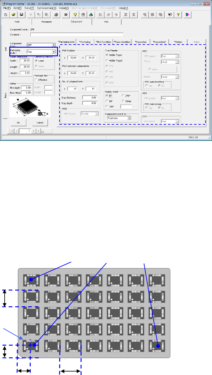
(3) Tray input method
1) Pilot Position
Enter the distance from the tray outside to the center position (X, Y) of the first
tray component.
2) Pitch between components
Enter the pitch between components (Pitch X, Pitch Y).
3) No. of columns/rows
Enter the number of components (Xn, Yn) in the lateral direction and the
longitudinal direction.
After the pickup data supply position is determined, the coordinates of 3 positions
of the tray are displayed in the pickup data. (X
1
, Y
1
to X
3
, Y
3
)
First component position X
First component
position Y
First
component
Pitch X
Pitch Y
(
X
2
,Y
2
)
(
X
1
Y
1
)
(
X
3
Y
3
)
EPU Instruction Manual Chapter 4 Creating a Production Program
4-60
4) Tray thickness
Enter the height "T" from the bottom side of a tray to the top side including the
component body.
If the thickness of a tray of an MTS exceeds 9 mm, any tray base cannot be set one level
higher.
The maximum tray thickness “T” is 23 mm.
5) Tray depth
Enter the depth of the tray.
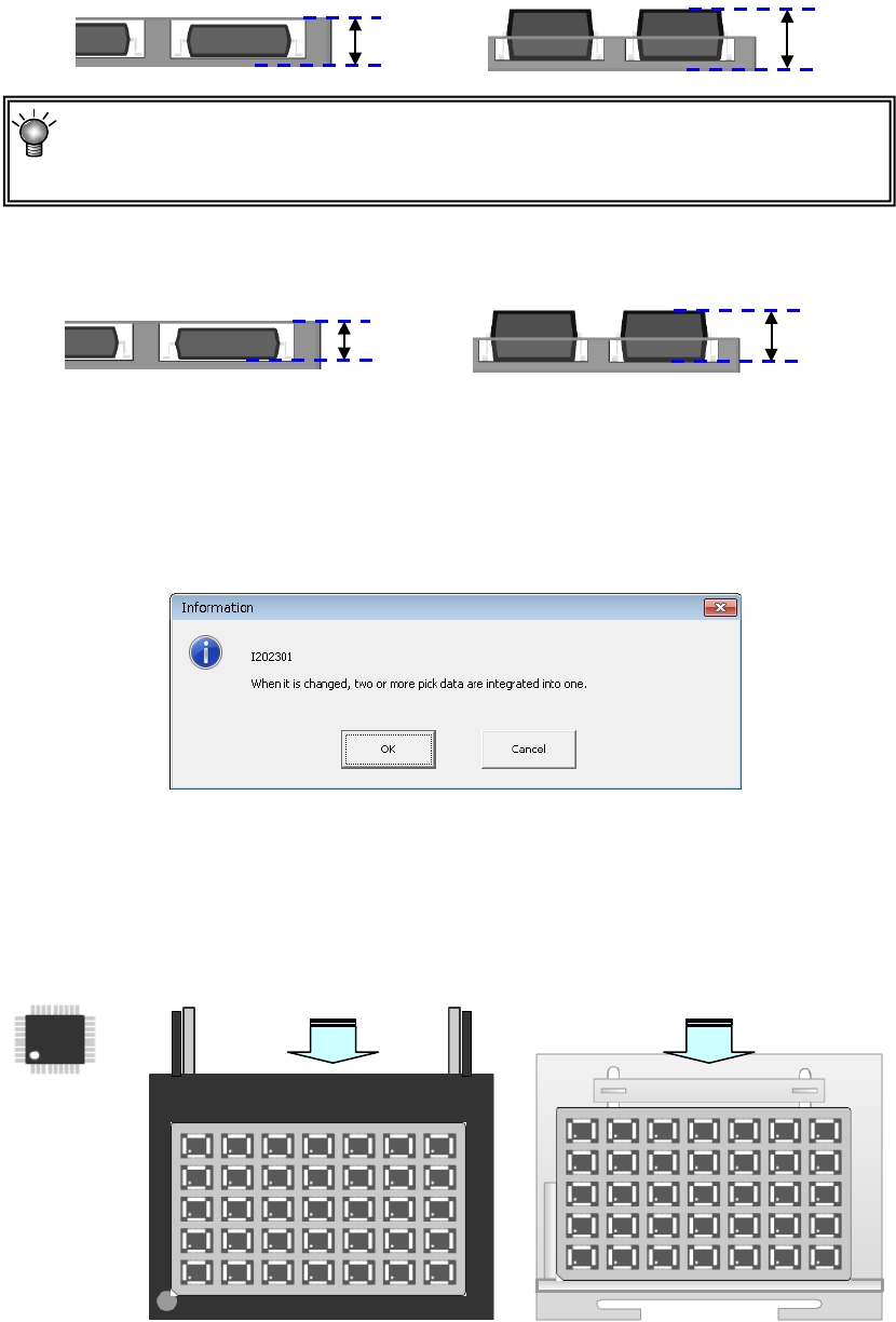
6) Tray feeder
Select a tray feeder from between “Holder” and “MTS.” (DTS, MTC, and MDS
cannot be set.)
If you change the setting of a tray feeder of a component for which two or more
records of pick data have been entered, the following message appears on the
screen.
7) Supply angle
Enter the direction of the component package on the tray in comparison with the
reference posture 0º (placement angle 0º).
For details, see "(1) Tape input method * JUKI component feed angle definition."
When you select “Other,” enter the angle in the edit field. (0º to 359.9875º)
8) Component reject to
Set the component discarding method for a case where centering results in a
recognition error or lead floating inspection results in an error. For details, see
"(1) Tape input method, Component discarding."
Tray depth
Tray depth
Tray
thickness “T”
Tray
thickness “T”
Angle definition 0°
供給角度 180°
供給角度 0°
Feed angle 0°
Feed angle 180°
Supply from the rear bank
Supply to the MTS