JX-350_EPU使用说明书.pdf - 第58页
EPU Instruction M anual C hapter 4 Creating a Production Progr am 4- 10 (3) PW B layout offset Enter the PW B layout endpoint vi ewed from t he PW B or igin her e. Enter the distance f rom the PW B orig in defined by the…
EPU Instruction Manual Chapter 4 Creating a Production Program
4-9
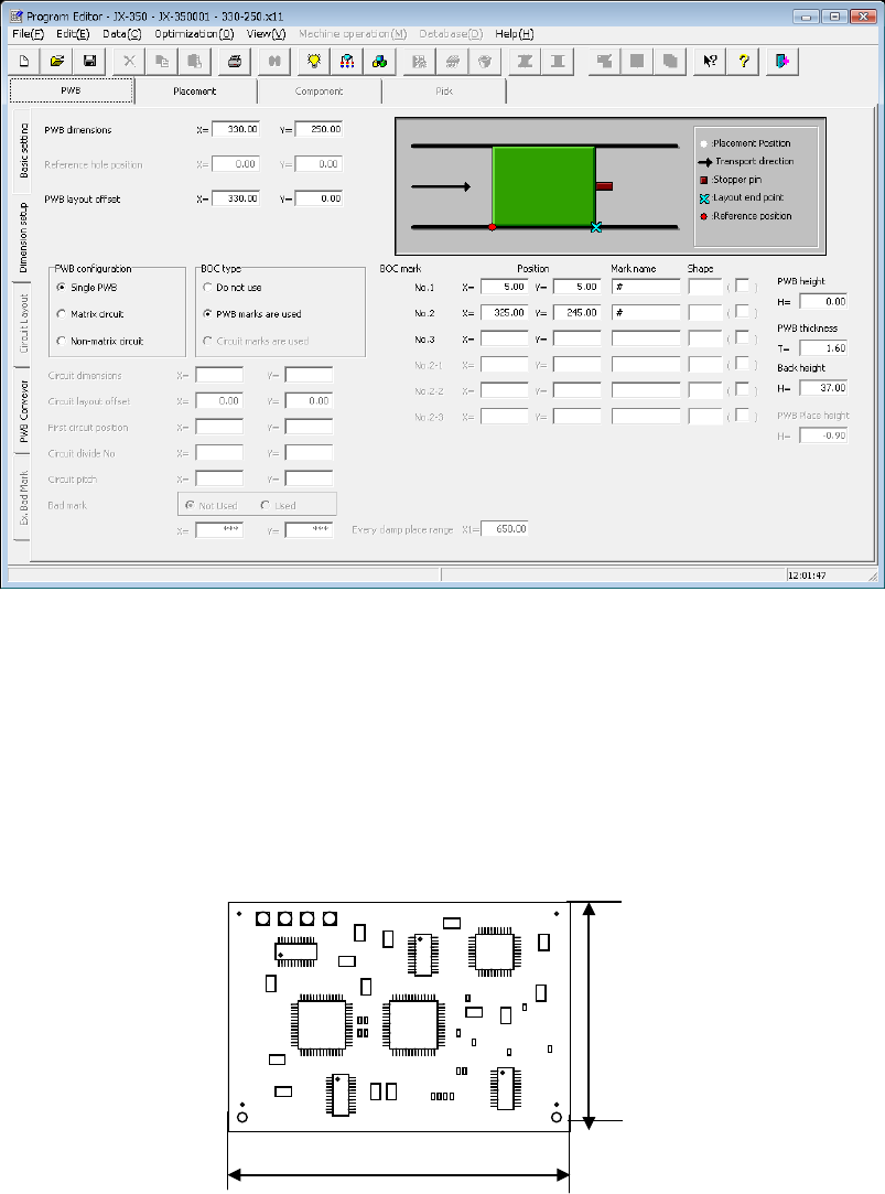
4.1.2.2.2 Dimension settings (single circuit PWB)
This selection specifies a PWB on which only one circuit is located.
(1) PWB dimensions
Enter the dimensions of a PWB here.
If the machine is supplied with a dummy PWB, enter the dimensions of this PWB
also.
The same direction as the PWB transport direction will be X and the vertical direction
to the PWB transport direction will be Y.
(2) Reference hole position
* Not used in JX-350.
Dimension X
Dimension Y
EPU Instruction Manual Chapter 4 Creating a Production Program
4-10
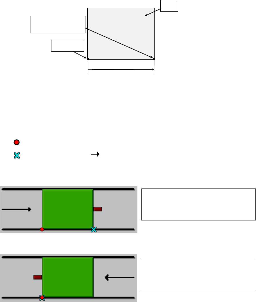
(3) PWB layout offset
Enter the PWB layout endpoint viewed from the PWB origin here.
Enter the distance from the PWB origin defined by the CDA or other tool to the
reference position (PWB layout endpoint) if the specified origin (the CAD origin or an
origin that is unique to a user) must be used as the PWB origin, for example, in a
case in which CAD data is used.
If the PWB transport side is the front, the PWB transport direction is from left to right,
and the PWB origin is located at the left bottom corner of the PWB, enter (Xb, 0) to
the “X” and “Y” coordinates fields of “Reference hole position.” A value “Xb” should be
positive.
Example: When the lower left corner is specified as a PWB position reference (Unit: mm)
① For front reference and PWB transport direction of L → R:
② For front reference and PWB transport direction of R → L:
(4) PWB configuration
For this item, select [Single circuit].
After the multi-circuit matrix or multi-circuit non-matrix is changed into the single
circuit matrix, single circuit expansion is performed.
At this time, a confirmation message is displayed.
PWB dimensions X=165 Y=125
PWB layout offset X=165 Y=0
PWB dimensions X=165 Y=125
PWB layout offset X=0 Y=0
:PWB position reference
:
Transport direction
:Layout end
PWB origin
PWB
Yb = 0
Xb
PWB layout endpoint
(Reference position)
EPU Instruction Manual Chapter 4 Creating a Production Program
4-11
(5) BOC type
“BOC” is abbreviation of Board Offset Correction, and is a mark for correcting a
component placement position that helps the system to place a component on a
board more accurately. (It is called a “fiducial mark” also.)
♦ Do not use:
Select this radio button if you do not use a BOC mark at all.
♦ PWB marks/ref. ckt marks are used:
Select this radio button if you are to correct the coordinates of a component
placement position with using BOC marks.
♦ Circuit marks are used:
You cannot select this radio button for a single-circuit (plane) PWB.
(6) Circuit dimensions, Circuit layout offset, First circuit position, Circuit divide No,
Circuit pitch
You do not have to enter these menu items for a single-plane (circuit) PWB (You
cannot set any value in these fields either).
When you select the “Matrix circuit” radio button or the “Non-matrix circuit” radio
button as the “PWB configuration,” you have to specify these menu items.
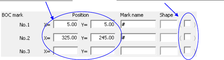
(7) BOC mark Position, Mark name, Shape
Enter the distance from the board reference position to the center of the BOC mark,
specify the mark name and teach the mark shape.
・ You can enter up to eight characters to specify the mark name.
・ Two or three BOC marks are required.
When you select the “Do not use” radio button as the “BOC type” on the “Dimension
setup” tab, these menu items are dimmed.
For details of the teaching operation, refer to Section 4.5.2 “Teaching” of the
“Instruction Manual CD” of the main unit for the detailed operations.
♦ If two points are used:
The difference between the designed dimension and the real dimension (or
measured dimension) and the error in the rotating direction can be corrected.
Leave the field for the third point blank. Further, if two or more marks exist on
the PWB, then select two points on the diagonal line that covers the entire area
for placement.
♦ If three points are used:
In addition to the case of two points, the right angle between X-axis and Y-axis can
be corrected.
JX-350 EPU is not applicable to the teaching.
Enter the X and Y coordinates.