JX-350_EPU使用说明书.pdf - 第80页
EPU Instruction M anual C hapter 4 Creating a Production Progr am 4- 32 4.1.2.4 PWB Conveyor This tab allows you to make the detailed setting s of t he conveyor and the support table. The “ PW B Conveyor ” screen cons is…
EPU Instruction Manual Chapter 4 Creating a Production Program
4-31
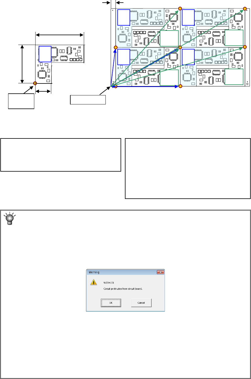
Example: Data entry example for a multi-plane non-matrix PWB
On the assumption that the lower left corner is the PWB position reference and the
lower left circuit is the reference circuit, an example of “circuit arrangement” is shown
below.
* This varies depending on the transport direction and reference (front and rear).
The setting method is the same as that for "multi-circuit matrix."
Area check
When you input the data screen (for example, when you select the “Placement data”
screen), the system performs an area check, that is, it checks that the entered
coordinates of the BOC mark and those of the bad mark are on a PWB (or a circuit), or
all circuits are located within a PWB.
If the system detects an error, the following warning message appears on the screen.
• When you click the <OK> button, the system resumes switching the screen to the
selected one.
• When you click the <Cancel> button, the system stops switching the screen
* If the warning message shown above appears on the screen, review each value
entered on the PWB data.
(Check the settings of “Reference hole position,” “PWB layout offset,” “First circuit
position,” “Circuit layout offset” and each coordinate entered on the “Circuit layout”
screen especially.)
PWB dimensions X=330 Y=200
PWB layout offset* X=330 Y=0
Circuit dimension X=150 Y=100
Ckt. Layout offset X=0 Y=0
Circuit No.1 X=15 Y=0
θ
=0
Circuit No.2 X=165 Y=100 θ=180
Circuit No.3 X=165 Y=0 θ=0
Circuit No.4 X=315 Y=100 θ=180
Circuit No.5 X=15 Y=100 θ=0
Circuit No.6 X=165 Y=200 θ=180
Circuit No.7 X=165 Y=100 θ=0
Circuit No.8 X=315 Y=200 θ=180
0°
180°
180°
180°
180°
Circuit
origin
PWB origin
0°
0°
0°
0°
120
10
30
15
Circuit 1 Circuit 2 Circuit 3 Circuit 4
Circuit 5 Circuit 6 Circuit 7 Circuit 8
EPU Instruction Manual Chapter 4 Creating a Production Program
4-32
4.1.2.4 PWB Conveyor
This tab allows you to make the detailed settings of the conveyor and the support table.
The “PWB Conveyor” screen consists of the “PWB conveyor” tab and the “Support table”
tab.
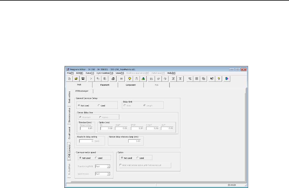
4.1.2.4.1 “PWB conveyor” tab
When you select the “PWB Conveyor” tab located at the lower left corner of each “PWB”
data screen, the following screen appears.
The “PWB conveyor” tab consists of the “General Conveyor Setup” group, the “Conveyor
motor speed” group and the “Option” group.
Each menu item displayed in the “General Conveyor Setup” group is explained below.
(1) Not Used/Used
Select whether to use the data set in the “General Conveyor Setup” group or not.
♦ Not Used: Select this radio button when you do not use the data in the “General
Conveyor Setup” group. The system operates according to the
settings of the main unit.
♦ Used: Select this radio button when you use the data in the “General
Conveyor Setup” group.
(2) Sensor delay time
Select whether to set the delay time of each sensor to the same value or not.
♦ Standard: Select this radio button to set the delay time of each sensor to the
same value.
♦ Option: Select this radio button to set the delay time of each sensor
respectively.
When you select the “Standard” radio button, the value set in the “Sensor delay” field
under the title “Standard” becomes active. When you select the “Option” radio
button, the delay time set in the field for each sensor under the title “Option” becomes
active.
EPU Instruction Manual Chapter 4 Creating a Production Program
4-33
(3) Delay Unit
Select the unit for the delay time of the conveyor sensor, “Time” (ms: 1/1000
second) or “Length” (mm).
♦ Time: Select this radio button to set the unit of the delay time to 1/1000 second
(ms).
♦ Length: Select this radio button to set the unit of the delay time to mm.
(4) Standard
When you select the “Standard” radio button in the “Sensor delay time” field, set the
delay time or delay length.
The allowable range for each unit is 0 to 2,500 (ms) and 0 to 1,000 (mm).
(5) Option
When you select the “Option” radio button in the “Sensor delay time” field, set the
delay time or delay length of each of the sensors: the IN sensor, the WAIT sensor,
the IN-COUNT sensor, the JOINT sensor, the OUT-COUT sensor and the OUT
sensor.
The allowable range for each unit is 0 to 2,500 (ms) and 0 to 1,000 (mm).
(6) Ready In delay setting
When the Ready IN signal, which is the signal for receiving the ejected board to be
input from the post process, is set to ON, the system passes the board to the post
process without stopping it. However, if you set the delay time here, the system
pauses when the OUT sensor detects a board, and when the Ready IN signal is set to
ON after the specified delay time passes, the system rotates the motor again to eject
the board. This delay time is useful for passing/receiving a board between the
machines whose board transporting speeds are different from each other. Note that
this delay time starts counting when the OUT sensor is set to ON.
(7) Sensor delay when re-clamp
Set the delay time to be applied if the system re-clamps a board without removing it
(re-clamping after reversing) when it restarts the production suspended due to a
production error such as a feeder float error.
You can set the delay time for each station, the right station and the left station. The
delay time range for each unit is 0 to 500 (ms) and 0 to 200 (mm).
Each menu item displayed in the “Conveyor motor speed” group is explained below.
(8) Not Used/Used
Select whether to use the settings made in the “Conveyor motor speed” group or not.
♦ Not Used: Select this radio button if you do not use the settings made in the
“Conveyor motor speed” group. The system operates according to
the settings made with the main unit.
♦ Used: Select this radio button if you are to use the settings made in the
“Conveyor motor speed” group.
(9) Transferring PWB
Set the transport speed to carry the PWB to the center buffer.
(10) Next Process
Set the speed for transporting a board on which components are placed to eject it to
the post process.