JX-350_EPU使用说明书.pdf - 第158页
EPU Instruction M anual C hapter 4 Creating a Production Progr am 4- 110 4.2.2.3 Feeder layout The [Feeder layout] command displays the f eeder layout specified on the “ Pick ” data screen gr aphically . W hen you click …
EPU Instruction Manual Chapter 4 Creating a Production Program
4-109
a) “Show permanent nozzle only” check box:
Checked: The system displays the nozzle layout of the ATC that is
output with the “Optimization” utility.
Not checked: The system displays the layout of the permanent nozzles only
that are set on the “EPU setup” screen.
b) Layout on the ATC display
Nozzle number displayed in red:
indicates a nozzle output with the Optimization function.
Nozzle number displayed in black:
indicates a permanent nozzle set on the “EPU setup” menu.
c) Number of nozzles
Ordinary status: Number of nozzles set by EPU setup.
Optimization: Required number of nozzles that is output by optimization.
EPU Instruction Manual Chapter 4 Creating a Production Program
4-110
4.2.2.3 Feeder layout
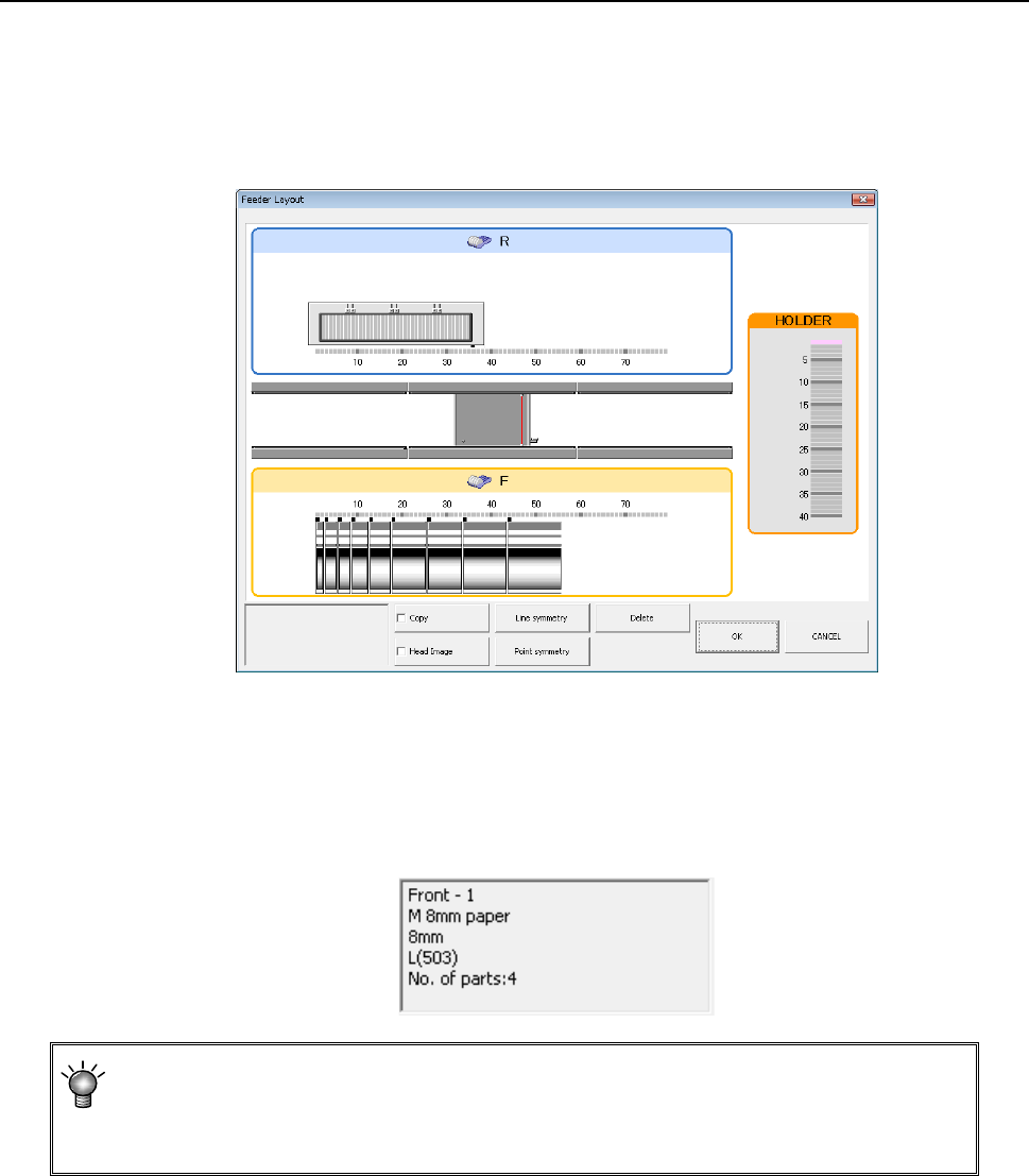
The [Feeder layout] command displays the feeder layout specified on the “Pick” data
screen graphically.
When you click the [Display]/[Feeder layout] commands from the menu, the following
“Feeder layout” window appears on the screen.
(1) “Feeder layout” window
1) When you move the trackball over the figure of a feeder displayed on the “Feeder
layout” window, part of the Component data for the corresponding feeder is
displayed on the screen.
As the feeder information, a component pick-up position, a component supply unit,
a component name, a number of a nozzle used for picking up a component and
the quantity of components (when optimized) are displayed on the screen
All centering methods specified on the “Component” data screen appear as the
“Centering method (nozzle number).” Although the centering method (nozzle number)
that cannot be handled with a certain model appears on the screen, the Optimization
function assigns the centering methods (nozzle numbers) that can be handled with the
model.
EPU Instruction Manual Chapter 4 Creating a Production Program
4-111
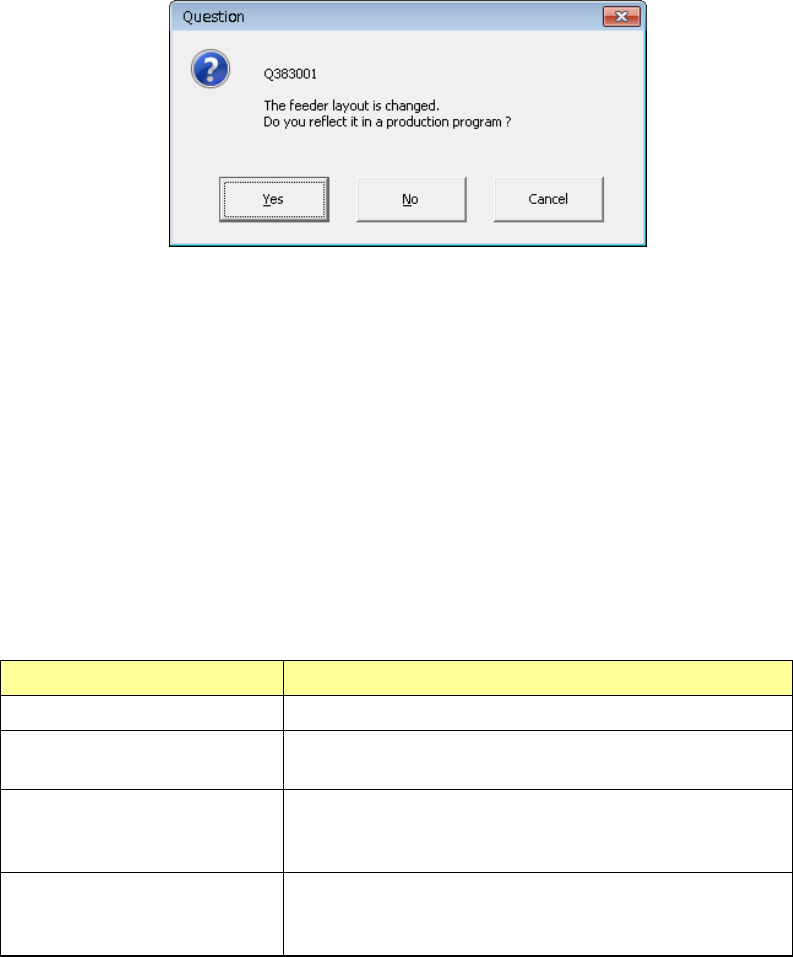
(2) Editing data on the “Feeder layout” window
You can edit the feeder layout with a mouse on the “Feeder layout” window.
After editing the feeder layout and closing the “Feeder layout” window, the following
message appears on the screen that asks you whether to incorporate your editing to
the program.
•
Yes: Incorporates your change(s) into the program data, and quits the
“Optimization” screen. The Pick data is changed according to your
editing.
•
No: Quits the “Optimization” screen without saving your change(s).
•
Cancel: Returns to the screen that allows you to select a feeder layout.
1) Selecting a feeder
Before moving, coping or deleting a feeder, select the feeder whose layout you
want to edit. The selected feeder appears in the way that you can distinguish it
from others clearly. The system provides you with the following ways for
selecting a feeder.
Operation Result
Click a feeder. The clicked feeder is selected.
Drag a mouse to surround a
feeder.
Feeders in the rectangle that is created with your drag
operation are selected.
Point a feeder with holding
down the “CTRL” key.
If any feeder is already selected, the selected feeder(s) and
feeders pointed while you are holding down the “CTRL” key
are all selected.
Point a feeder with holding
down the “SHIFT” key.
Feeders located between the feeder you selected for the
first time and feeders pointed while holding down the
“SHIFT” key are all selected