JX-350_EPU使用说明书.pdf - 第120页
EPU Instruction M anual C hapter 4 Creating a Production Progr am 4- 72 ( 3) Pi cking offset XYZ: S pecif y the distance f rom the cent er of a component to t he component pick - up position in the “ Pick ing offset XY ”…
EPU Instruction Manual Chapter 4 Creating a Production Program
4-71
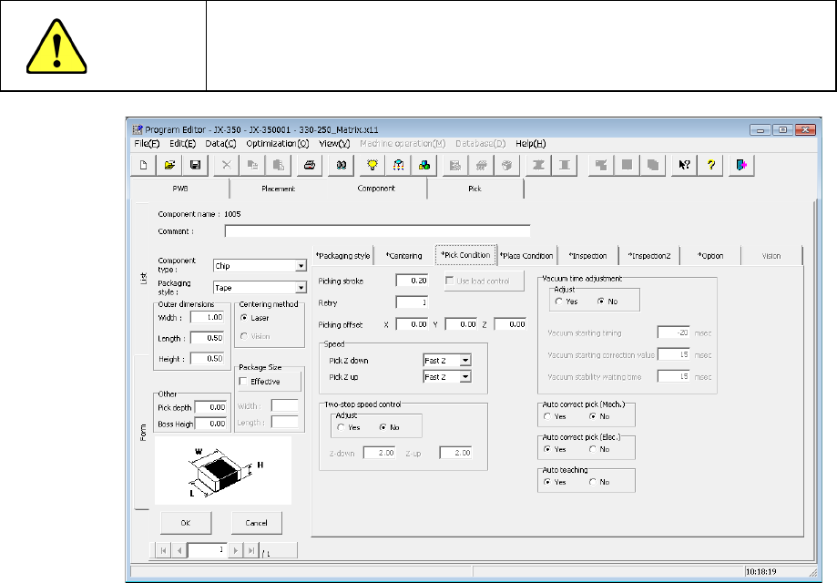
4.1.4.2.4 Pick Condition
Pick conditions are setting items for pickup and the default values are applied.
Accordingly, they do not need to be changed. If pickup cannot be performed in the
default value status, change the settings.
CAUTION
If you change any of the basic settings after changing any value on
the “Pick Condition” tab, some values are reset to their defaults on
the “Pick Condition” tab.
(1) Picking stroke:
Specify the distance for pushing a component during component pick-up.
If you set “0” here, the nozzle may not reach a component and may not pick up the
component, or a chip rise error may occur due to the variation of component heights.
In such a case, enter the larger value (that is, by entering a positive value) so that the
nozzle can reach a component.
The initial value is “0.2 mm” (0mm for a 0603 component).
"The load is controlled" button becomes effective for the use of the nozzle with which
a simple load can be controlled after 601.
* Not used in JX-350.
Note) The picking stroke is corrected when picking up components supplied from
the electric feeder (except for 0603 component).
(2) Retry:
Set the number of times the system will pick up a component again if a component
pick-up error occurs during production.
If "1" is set here, two successive picking errors will cause a "component run-out
error."
If a retry over error occurs during PWB production, the signal light flashes in yellow to
notify you of the error.
EPU Instruction Manual Chapter 4 Creating a Production Program
4-72
(3) Picking offset XYZ:
Specify the distance from the center of a component to the component pick-up
position in the “Picking offset XY” field.
When you create Pick data, it is added to or subtracted from the initial value of “XY,”
which is automatically calculated.
When the machine cannot pick up a component normally because there is a
projection or dent in the center of the component, set this menu item.
In the “Picking offset Z” field, specify the distance from the tip of the nozzle to be
pushed when the system picks up a component.
When you create Pick data, the system adds this value to the initial value of “Z” that is
calculated automatically.
If the position obtained by shifting the coordinates of the component center by the
offset is regarded as the component pick-up position, this component pick-up
position may not be within the outer dimensions of the component due to rotation
or other movement of the component. Therefore, the system handles the outer
dimensions according to this effect.
Even though you change the value specified in the “Picking offset XYZ” field after
coordinates of a component pick-up position is specified, the system will not
recalculate the coordinates of the component pick-up position. To do so, change
the setting of the “Side” field to “AUTO” on the “Pick” data screen for a component
associated with the component data you changed, and specify the pick-up
position again. The system will calculate the coordinates of the component
pick-up position again, and change the value in the “Z” field also.
(4) Pick Z down/Pick Z up
Select the speed at which the Z-axis moves when a component is picked up.
When you select the low speed, the operation becomes more stable, but the cycle
time takes longer.
(5) Tw o-step speed control
Specify whether to control the speed at which the nozzle moves up and down in two
steps when a component is picked up.
When you select the “Yes” radio button in the “Adjust” field, enter the height to be
controlled in two steps for moving up and moving down the nozzle respectively.
The speed changes at the position specified from the upper surface of the PWB.
Though it moves to the specified position at high speed, it operates from there to the
PWB side at low speed, and components are placed. When the lead components
are placed, it is set to prevent the lead bending.
(6) Vacuum time adjustment
Specify whether to adjust the vacuum time or not.
When you select the “Yes” radio button in the “Adjust” field, enter a value in each of
the “Vacuum starting timing” field, the “Vacuum starting correction value” field and the
“Vacuum stability waiting time” fields in unit of ms.
When you use a gripper nozzle, the system does not make any adjustment when it
picks up a component.

EPU Instruction Manual Chapter 4 Creating a Production Program
4-73
(7) Auto correct pick:
This setting causes the system to automatically correct the component pick-up
position error as the result of laser recognition. Note that this check is only for
components that are centered with laser and supplied from tape.
The corrected position is entered to the coordinates field of the component pick-up
position on the “Pick” data screen.
The system corrects the component pick-up position without causing the
simultaneous pick-up to be disordered by correcting the pitch in Y direction when an
electric feeder is used.
When you select a component pick-up position correction for a mechanical
feeder, the system may not be able to pick up a component simultaneously on
the way because the component pick-up coordinates change during PWB
production.
(8) Auto teaching:
This is the function for automatically measuring the center of a component when the
system tracks the component pick-up position.
You cannot select the “Yes” radio button for components other than chips 0603 to
3216 whose packaging style is a paper tape (8-mm pitch).
When you select “Yes,” the system automatically teaches the center of a component
when it tracks the pick-up position.