JX-350_EPU使用说明书.pdf - 第83页
EPU Instruction M anual C hapter 4 Creating a Production Progr am 4- 35 4.1.2.5 “ Ex. Bad Mark ” screen For the extended bad mark , enter the "bad mar k" posit ion for each circuit f rom the "PW B ref eren…
EPU Instruction Manual Chapter 4 Creating a Production Program
4-34
Each menu item displayed in the “Option” group is explained below.
(11) Not Used/Used
Select whether to use the function for supporting a board having a notch with the
WAIT sensor or not.
♦ Not Used: Select this radio button if you do not use the function for supporting a
board having a notch with the WAIT sensor.
The system operates according to the settings made with the main
unit.
♦ Used: Select this radio button if you are to use the function for supporting a
board having a notch with the WAIT sensor.
(12) Hold Wait/IOINT Sensor active until PWB moves out
When you check this check box, the function for supporting a board having a notch
with the WAIT sensor is enabled.
When you deselect this check box, the function above is disabled.
EPU Instruction Manual Chapter 4 Creating a Production Program
4-35
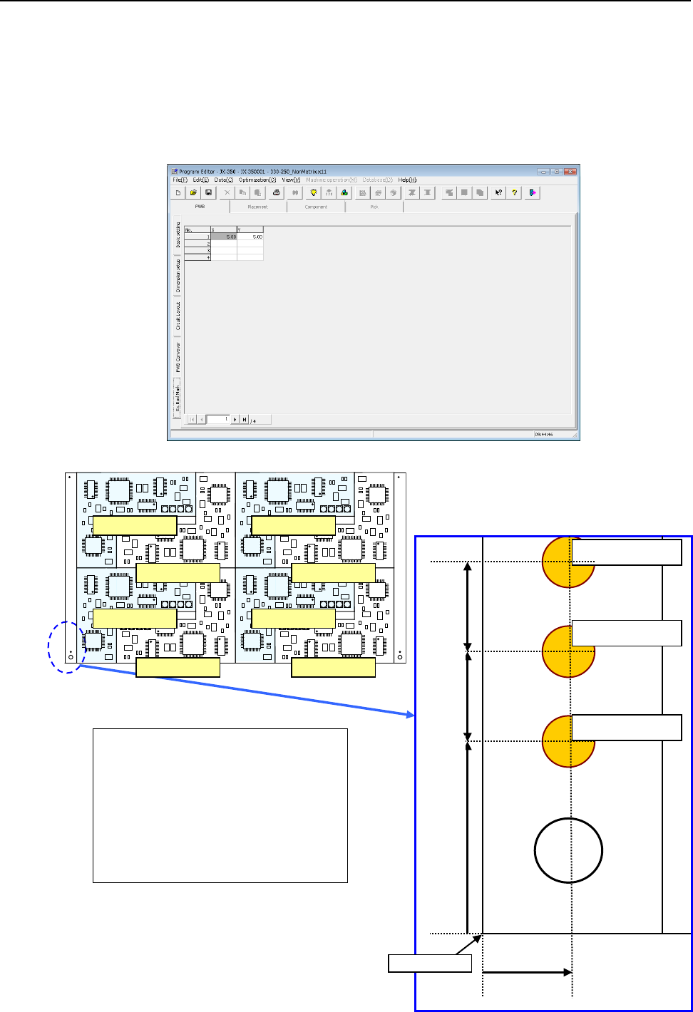
4.1.2.5 “Ex. Bad Mark” screen
For the extended bad mark, enter the "bad mark" position for each circuit from the "PWB
reference position."
Use this mark when the head moving distance for recognition is shortened or a mark
cannot be created in the circuit.
When you use an extended bad mark, enter the coordinates of a bad mark on each circuit.
When you select the “Ex. Bad Mark” tab displayed on the lower left of each “PWB” data
screen, the following screen appears.
Circuit No.1 X=5 Y=10
Circuit No.2 X=5 Y=17
Circuit No.3 X=5 Y=24
Circuit No.4 X=5 Y=31
Circuit No.5 X=5 Y=38
Circuit No.6 X=5 Y=45
Circuit No.7 X=5 Y=52
Circuit No.8 X=5 Y=59
For circuit No.1
For circuit No.2
For circuit No.3
5mm
10mm
7mm
7mm
PWB origin
Circuit No.1
Circuit No.3
Circuit No.4
Circuit No.2
Circuit No.5
Circuit No.6
Circuit No.7
Circuit No.8
EPU Instruction Manual Chapter 4 Creating a Production Program
4-36
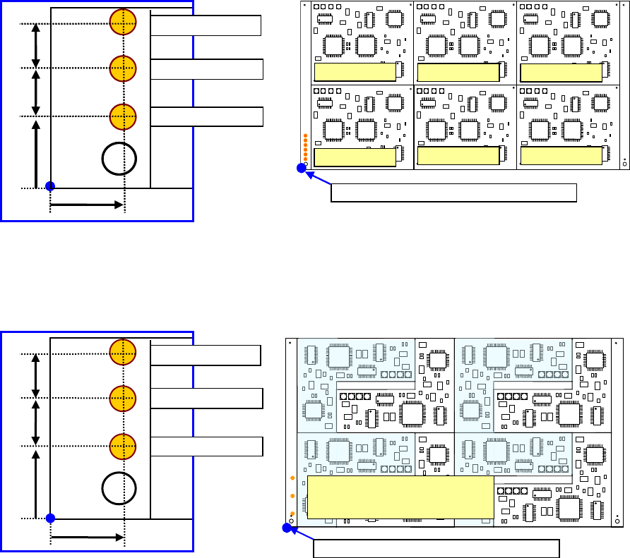
♦ Multi-circuit matrix
The order of circuits is the X-direction pitch/Y-direction pitch from the reference
circuit.
♦ Multi-circuit non-matrix
The order of circuits set by circuit arrangement is used.
For circuit No.1
For circuit No.3
10mm
7mm
For circuit No.2
5mm
7mm
PWB position reference [PWB origin]
Circuit No.4
PWB position reference [PWB origin]
Circuit No.1
Circuit No.2
Circuit No.3
Circuit No.5
Circuit No.6
For circuit No.1
For circuit No.3
10mm
7mm
For circuit No.2
5mm
7mm
The order may depend on
the circuit layout No.
For circuit No.1
For circuit No.3
10mm
7mm
For circuit No.2
7mm
5mm
PWB position reference [PWB origin]