JX-350_EPU使用说明书.pdf - 第98页
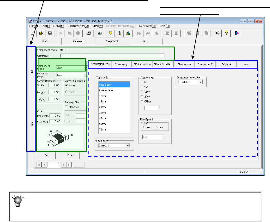
EPU Instruction M anual C hapter 4 Creating a Production Progr am 4- 50 4.1.4.2 Creating of com ponent data The component data creation screen ( component f orm) c onsists of 8 s creens ( "Pack aging" , "C…
EPU Instruction Manual Chapter 4 Creating a Production Program
4-49
When you select a “Component name” by double-clicking it on the “List” screen, the
“Form” screen for the selected component data appears so that you can create/edit its
component data.
The “Form” screen consists of the basic setting screen, “Packaging style” tab, “Centering”
tab, “Pick Condition” tab, “Place Condition” tab, “Inspection” tab, “Inspection 2” tab,
“Option” tab and “Vision” tab and displays data on only one component.
When no data is entered, the packaging style tab sheet is displayed but input items are
not displayed.
When the component packaging style of the basic section is entered, the corresponding
input items are displayed.
* JX-350 is not applicable to the vision component.
* Keyboard operation
To move the focus among the displayed items, press the TAB key(Shift + key)
.
To move the focus among pages, press the [PageUp] or [PageDown] key.
Tabs for switching the screen: “Form” screen and “List” screen
Data on the item you selected here appears on
the displayed area below.
Basic section
EPU Instruction Manual Chapter 4 Creating a Production Program
4-50
4.1.4.2 Creating of component data
The component data creation screen (component form) consists of 8 screens
( "Packaging", "Centering", "Pick condition", "Placement conditions", "Inspection",
"Inspection 2", "Option", and "Vision") including the basic section.
However, items that need your setting are only on the initial screen (including the
information of "Packaging style").
For other items, the initial values are already registered. Enter data for necessary items
only.
Most of recognition errors and other various initial errors after program preparation
can be solved by reviewing the component data. If this is the case, make
adjustment by changing the component height as well as those values set as the
"initial values" described above.
4.1.4.2.1 Initial screen
(1) Component name
The component name is displayed. (The name used for placement data is displayed
but cannot be edited.)
(2) Comment
Enter a comment here for those components that are hard to be recognized only by
their component name. You can omit the “Comment.”
Up to 127 characters can be entered.
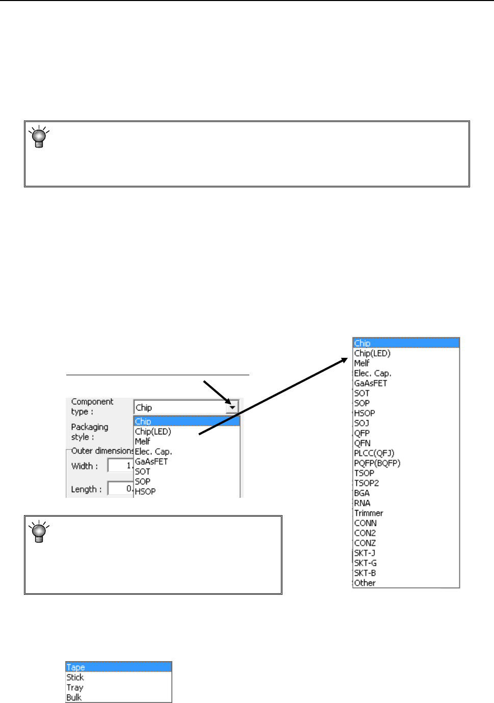
(3) Component type
Select a component type from the pull-down list.
If you happen to select a wrong component
type, a recognition error or other error occurs
when the corresponding component is
centered. Be sure to select a correct
component type.
(4) Packaging style
From the displayed "Packaging style" list, select a component supply device. To
change it, select a packaging style from the pull-down list.
Select a component type from he display list.
EPU Instruction Manual Chapter 4 Creating a Production Program
4-51
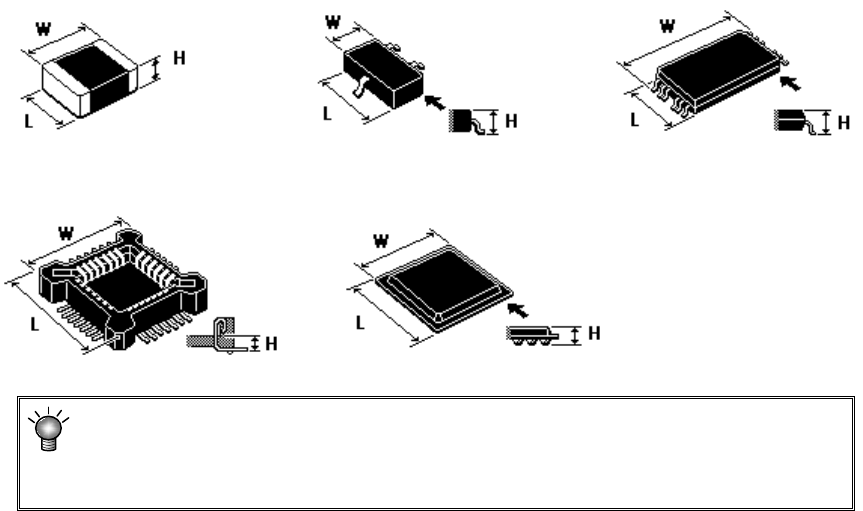
(5) Outer dimensions
Enter outer dimensions of component matched to each component type.
Enter them by referring to the component illustration shown in the lower left part of
the form screen. Note that there are 2 cases, namely, one where the lead is
included and the other where the lead is not included, depending on the component
type.
The graphic data based on JUKI component feed angle definition 0° is displayed
according to "Component type."
Example: W = Outer dimension, horizontal
L = Outer dimension, vertical H: Component height
♦
Square chip ♦SOT ♦T-SOP
♦ Socket ♦BGA
If you enter the dimensions oppositely, that is, enter the width (horizontal) to the
“Length” field or vice versa, the system may not be able to center the component.
If a wrong component height is entered, a laser recognition error may be easily
caused by unstable laser measuring position.