JX-350_EPU使用说明书.pdf - 第78页
EPU Instruction M anual C hapter 4 Creating a Production Progr am 4- 30 (2) Checking t he setting s of circ uits to be placed on a board To check the sett ings of circuits to be placed on a boar d, press t he [Confir mat…
EPU Instruction Manual Chapter 4 Creating a Production Program
4-29
Specification of a circuit to be placed on a board has the following functions.
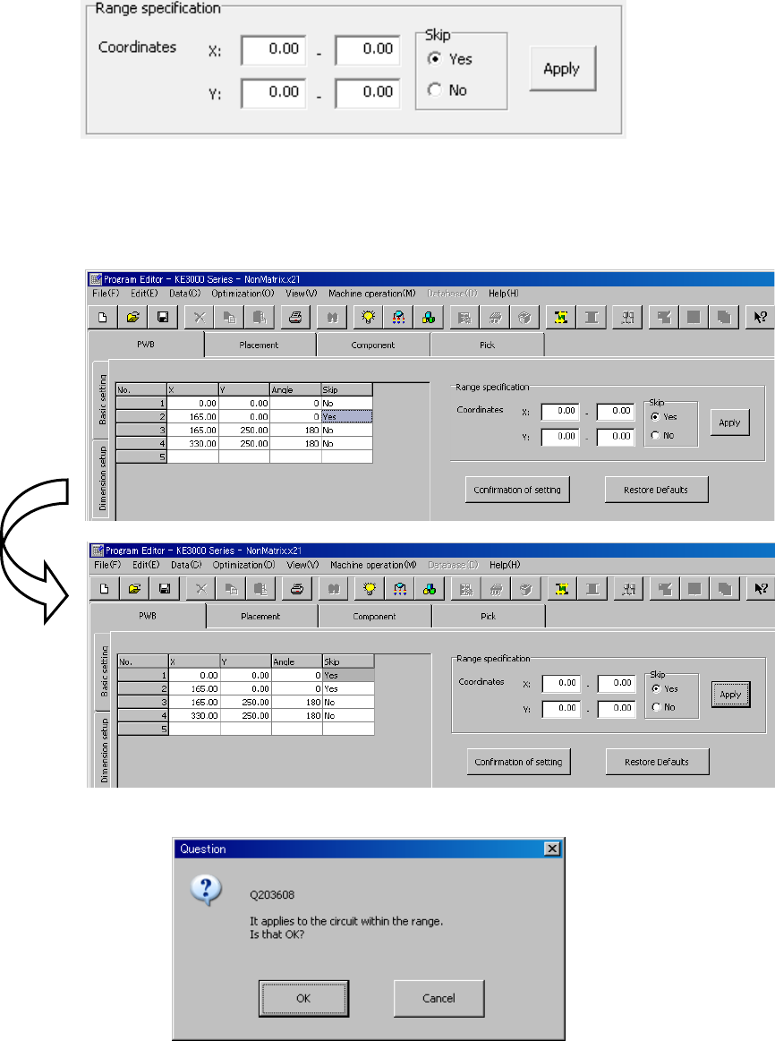
(1) Setting circuits by specifying the range of the origin coordinates
This function sets all circuits whose origin coordinates are located in the specified range
of the X coordinate and in the specified range of the Y coordinate respectively so that
they will be placed on a board. Enter the X coordinate range and the Y coordinate range
respectively, and then select the “Yes” radio button or the “No” radio button for the menu
item “Skip.” Next, press the [Apply] button to specify whether all circuits located in the
specified range will be placed on a board or not.
When you press the [Apply] button on the figure above, the settings of circuits in the list
are changed as shown below.
Note that although the “Skip” setting of the circuit whose origin is in the specified range,
the circuit “No. 1,” is changed to “Yes,” the setting of any other circuits does not change.
Therefore, the “Skip” setting of circuits other than this circuit is not changed to “No” either.
Note that when you press the [Apply] button, the following “Question” dialog box appears
on the screen.
EPU Instruction Manual Chapter 4 Creating a Production Program
4-30
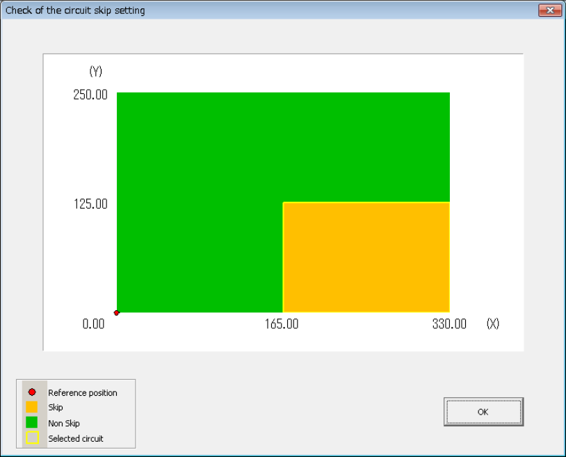
(2) Checking the settings of circuits to be placed on a board
To check the settings of circuits to be placed on a board, press the [Confirmation of
setting] button. The “Check of the circuit skip setting” screen shows the board reference
position, a circuit(s) to be skipped and a circuit selected currently.
(3) Restore Defaults
When you press the [Restore Defaults] button, the “Skip” settings of circuits are returned
to the default settings. All circuits are not to be skipped (“No”) by default.
EPU Instruction Manual Chapter 4 Creating a Production Program
4-31
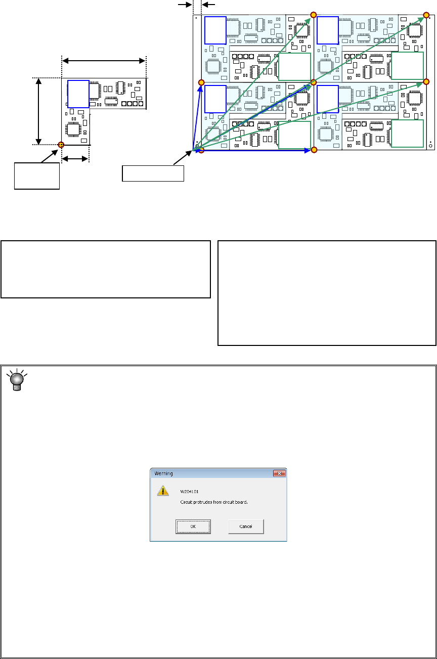
Example: Data entry example for a multi-plane non-matrix PWB
On the assumption that the lower left corner is the PWB position reference and the
lower left circuit is the reference circuit, an example of “circuit arrangement” is shown
below.
* This varies depending on the transport direction and reference (front and rear).
The setting method is the same as that for "multi-circuit matrix."
Area check
When you input the data screen (for example, when you select the “Placement data”
screen), the system performs an area check, that is, it checks that the entered
coordinates of the BOC mark and those of the bad mark are on a PWB (or a circuit), or
all circuits are located within a PWB.
If the system detects an error, the following warning message appears on the screen.
• When you click the <OK> button, the system resumes switching the screen to the
selected one.
• When you click the <Cancel> button, the system stops switching the screen
* If the warning message shown above appears on the screen, review each value
entered on the PWB data.
(Check the settings of “Reference hole position,” “PWB layout offset,” “First circuit
position,” “Circuit layout offset” and each coordinate entered on the “Circuit layout”
screen especially.)
PWB dimensions X=330 Y=200
PWB layout offset* X=330 Y=0
Circuit dimension X=150 Y=100
Ckt. Layout offset X=0 Y=0
Circuit No.1 X=15 Y=0
θ
=0
Circuit No.2 X=165 Y=100 θ=180
Circuit No.3 X=165 Y=0 θ=0
Circuit No.4 X=315 Y=100 θ=180
Circuit No.5 X=15 Y=100 θ=0
Circuit No.6 X=165 Y=200 θ=180
Circuit No.7 X=165 Y=100 θ=0
Circuit No.8 X=315 Y=200 θ=180
0°
180°
180°
180°
180°
Circuit
origin
PWB origin
0°
0°
0°
0°
120
10
30
15
Circuit 1 Circuit 2 Circuit 3 Circuit 4
Circuit 5 Circuit 6 Circuit 7 Circuit 8