JX-350_EPU使用说明书.pdf - 第184页
EPU Instruction M anual C hapter 4 Creating a Production Progr am 4- 136 4.4 Pr oduction M a nagement I nform ation ( Window ) W hen you select “ PW B pr oduction ” as t he production m ode, the product ion management in…
EPU Instruction Manual Chapter 4 Creating a Production Program
4-135
●When using a server Component database.
Select "Server Component part DB".
In this case, the reference database will automatically refer to the database in the
server of the production support system.
The IP address and port number of the production support system server are
displayed on the screen
※
For more information Chapter 5 database for the database in the mounter side,
set in the production support system side, please refer to in the instruction manual
of the production support system.
(4) Default Nozzle Selection
Specify the nozzle you use among the “No. 500 nozzles” and the “No. 502/503
nozzles.” This selection changes the nozzle number the system automatically selects
on the “Component” data screen.
Example: When you select the radio button “Use 500 nozzle as default”
When you enter “2 mm × 1.2 mm” as the component dimensions on the “Component”
data screen, the system automatically selects a “No. 500 nozzle.”
(5) Setting “Pick Position Check”
When you are to check the component pick-up position, enter the value for judging if a
pick-up position is shifted from the regulated position.
See the description of the pick position detection under Section 4.1.4.2.6 “Inspection”
for the threshold value and the judgment value (“Tolerance”) for detecting a pick-up
position error.
(6) Default Feeder
If an 8-mm electric feeder is specified in the Pick data, select the initial feeder type, “E
8mm S” (single lane) or “E 8mm D” (double lane). “E 8mm S” is selected by default.
EPU Instruction Manual Chapter 4 Creating a Production Program
4-136
4.4 Production Management Information (Window)
When you select “PWB production” as the production mode, the production management
information is saved. This section describes the production management information
saved during production.
4.4.1 Production management information
(1) Conditions under which the production management information is collected
① When “PWB production” is selected as the production mode, and components are
placed on all component placement positions of a board
② Once the information is collected, new information collected during the next
production is added to the previous production management information.
If you want to collect new data only, clear the information already stored.
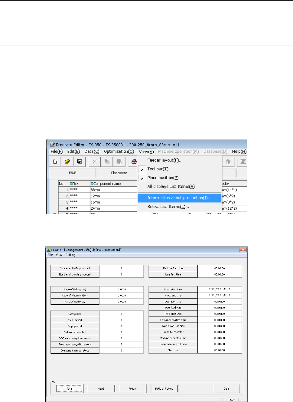
(2) Production management information screen
Click the [View] command from the menu bar, and select the “Information about
production” to be displayed on the screen.
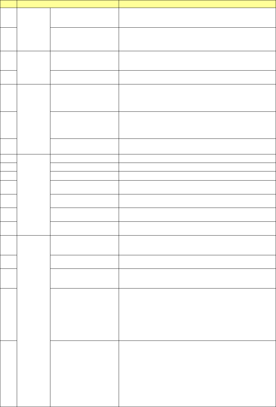
(3) Contents
1) Production management information (All)
EPU Instruction Manual Chapter 4 Creating a Production Program
4-137
No.
Menu item
Description
1
PWB
production
Number of PWBs
produced
Number of PWBs already produced after the production
management information was cleared the last time (number of
PWBs produced completely only)
2
Number of circuits
produced
Number of circuits already produced
(Number of PWBs produced × Number of circuits – Number
of bad marks detected)
3
Ta c t
Machine Tact
Shows the time from when one board is loaded into the
machine until when the board is ejected..
The cycle time per station is displayed also.
4 Line Tact
Shows the time from when one board is ejected until when the
next board is ejected.
5
Ratio
Ratio of Pick-up (%)
Shows the successful component pick-up ratio.
(Number of successful component pick-ups / (Number of
successful component pick-ups + Number of component
pick-up errors) )
×
100
6 Ratio of Placement (%)
Shows the successful component placement ratio.
(Number of successful component placements / (Number of
successful component placements + Number of component
placement errors))
×
100
7 Ratio of Retry (%)
Shows how frequently a component pick-up retry has occurred.
100 – “Ration of Pick-up”
8
Number
Total picked
Total number of picked-up components
9
Cmp. picked
Total number of components picked up successfully
10 Cmp. placed Total number of components placed successfully
11 Bad marks detected
The total number of circuits for which bad mark is detected and
detected area bad marks.
12
BOC mark recognition
errors
Number of BOC mark recognition errors that have occurred
13
Area mark recognition
errors
Number area mark recognition errors that have occurred
14 Component run out stops
How many times the machine stopped due to a component
run-out error
15
Time
Prod. start time
Date and time the machine started PWB production for the first
time after clearing the production management information last
time.
16 Prod. end time
Date and time the machine finished PWB production with this
production program last time.
17 Operation time
Accumulated time from when PWB production started until
when it finished excluding stop time and waiting time for a
board (pause is not included in this time period)
18 PWB load wait
Shows the accumulated time periods from when the clamped
board was released and the Out sensor was turned off till when
the In sensor was turned on.
If the In sensor or the Wait sensor was turned on from the start,
any time period is not included in this “PWB load wait” time.
Any time period the machine paused while it was waiting for a
PWB to be loaded is not included in this “PWB load wait” time
either.
19 PWB eject wait
Shows the accumulated time periods from when the Out sensor
was turned on till when it turned off after the clamped board was
released.
If the Out sensor was turned on from the start, any time period
is not included in this “PWB eject wait” time.
However, if a PWB was the last one, the time passed till this
last board finished being transported is include in this “PWB
eject wait” time regardless of the Out sensor state, on or off.
Any time period the machine paused while it was waiting for a
PWB to be ejected is not included in this “PWB eject wait” time.