JX-350_EPU使用说明书.pdf - 第110页
EPU Instruction M anual C hapter 4 Creating a Production Progr am 4- 62 (4) How to enter data if you select “ Bulk ” as the “ Packag ing style ” 1) Ty p e Set the bulk f eeder type. 2) Feed w ait ing tim e Set the ratio …
EPU Instruction Manual Chapter 4 Creating a Production Program
4-61
9) MTC
* JX-350 is not applicable to the MTC.
10) MTS
• MTS speed Specify the tray pull-out speed. This prevents lightweight
components from jumping.
• MTS mark recognition ...
When the MTC is used, and the pick reference position mark recognition
is set to "Do," the pick reference position mark is recognized when the
tray where the set components are placed is pulled out, and the
execution coordinates such as the pick and the component return is
corrected.
It takes the recognition time though the pick accuracy improves when
"Do" is selected.
11) DTS
* JX-350 is not applicable to the DTS.
12) MDS
* JX-350 is not applicable to the MDS.
EPU Instruction Manual Chapter 4 Creating a Production Program
4-62
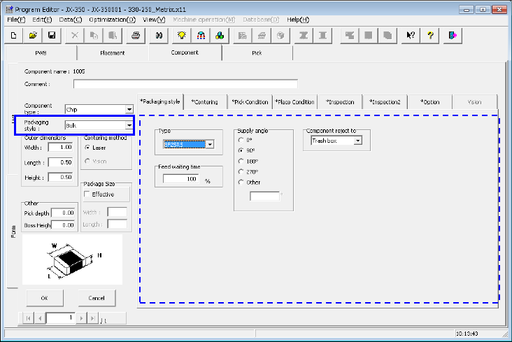
(4) How to enter data if you select “Bulk” as the “Packaging style”
1) Type
Set the bulk feeder type.
2) Feed waiting time
Set the ratio of the actual waiting time to the waiting time (that is, waiting time set
per feeder type) the system has to wait until it can pick up the next component
after picking up the current component on a percentage basis.
The initial value is 100 %.
3) Supply angle
Enter the angle of the component package on the stick feeder with respect to the
component placement angle, 0 degrees.
For details, see "(1) Tape input method * JUKI component feed angle definition."
When you select “Other,” enter the angle in the edit field. (0º to 359.9875º)
4) Component reject to
Set the component discarding method for a case where centering results in a
recognition error or lead floating inspection results in an error.
For details, see "(1) Tape input method, Component discarding."
EPU Instruction Manual Chapter 4 Creating a Production Program
4-63
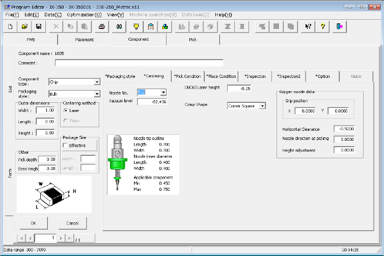
4.1.4.2.3 Centering
Set "Nozzle No.", "Component pick vacuum pressure", "LNC60 laser height",
"Component shape", and "Gripper nozzle data."
(1) Nozzle No.
Select the number of the nozzle that can pick up a component stably from the
pull-down list.
In the combo box list, the standard nozzle numbers (500 to 511), screw type nozzle
(7006), and other nozzle numbers assigned by setup are displayed.
(2) Vacuum level
Enter the pressure data for judging whether a component was picked up successfully
or not by the vacuum pressure.
When you select the “Nozzle No.,” this value is automatically set.
If the vacuum pressure is different from the automatically set value due to the shape
of the side of a component picked up or for another reason, you can change the value
displayed here.
To set this value manually, enter the vacuum pressure that is used to pick up a
component with the nozzle that is specified with the “Nozzle No.”
Since the finishing of the component surface may be different depending on its
manufacturer, we recommend that you measure the component on the “Machine
operation” menu.