JX-350_EPU使用说明书.pdf - 第113页
EPU Instruction M anual C hapter 4 Creating a Production Progr am 4- 65 SOT - γ γ = 0.25 SOP HSOP - 0.7 × t SOJ - 0.65 × t QFP - 0.7 × t QFN t - 0 . 5 t - 0.5 × t QFJ (PLCC) ※ LNC6 0 -(t - β ) β = 0. 4 QFJ(PLCC ) ※ FMLA …
EPU Instruction Manual Chapter 4 Creating a Production Program
4-64
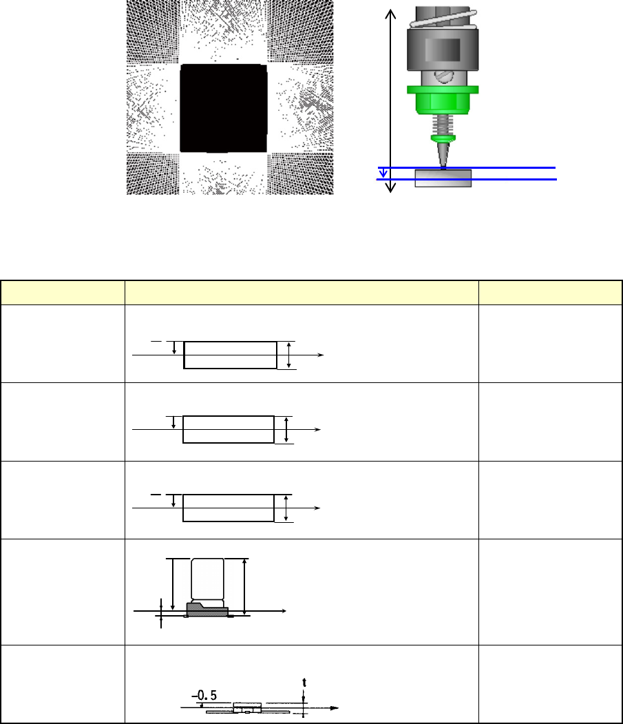
(3) LNC60 Laser position
Set the measurement height attained when the system centers a component with
laser.
Enter the distance from the nozzle tip to the measurement position to which the laser
beam is irradiated.
The initial value is automatically determined by the component height and the
component type. However, some components may require alteration of the initial
value. If such portions that do not intercept laser rays completely as the end of lead
and the top surface/bottom surface of component are at the laser height, a laser
recognition error may occur. Select a height that assures stable recognition (for
example, if the position measured with laser is cylindrical-shaped or
transparent-colored).
♦ Default Laser height
Default laser heights are set for some component types and heights.
Table shows the relation between component heights and default laser heights.
Component type Measurement position Laser height (mm)
Square chip
2
t
-
部品高さ t
レーザ測定位置
t
- -
2
Square chip
(LED)
部品高さ t
レーザ測定位置
- (t - 0.15)
- (t –0.15)
MELF
2
t
-
部品高さ t
レーザ測定位置
t
- -
2
Aluminum
electrolytic
capacitor
部品高さ t
レーザ測定位置
- ( t -
β)
β
- (t –β)
β= 0.35
GaAsFET
-0.5
-Z
0
Nozzle tip
Laser height
Component height
Component height
Measurement
position with laser
Measurement
position with laser
Component height
Measurement
position with laser
Component height
Measurement
position with laser
Component height
Measurement
position with laser
EPU Instruction Manual Chapter 4 Creating a Production Program
4-65
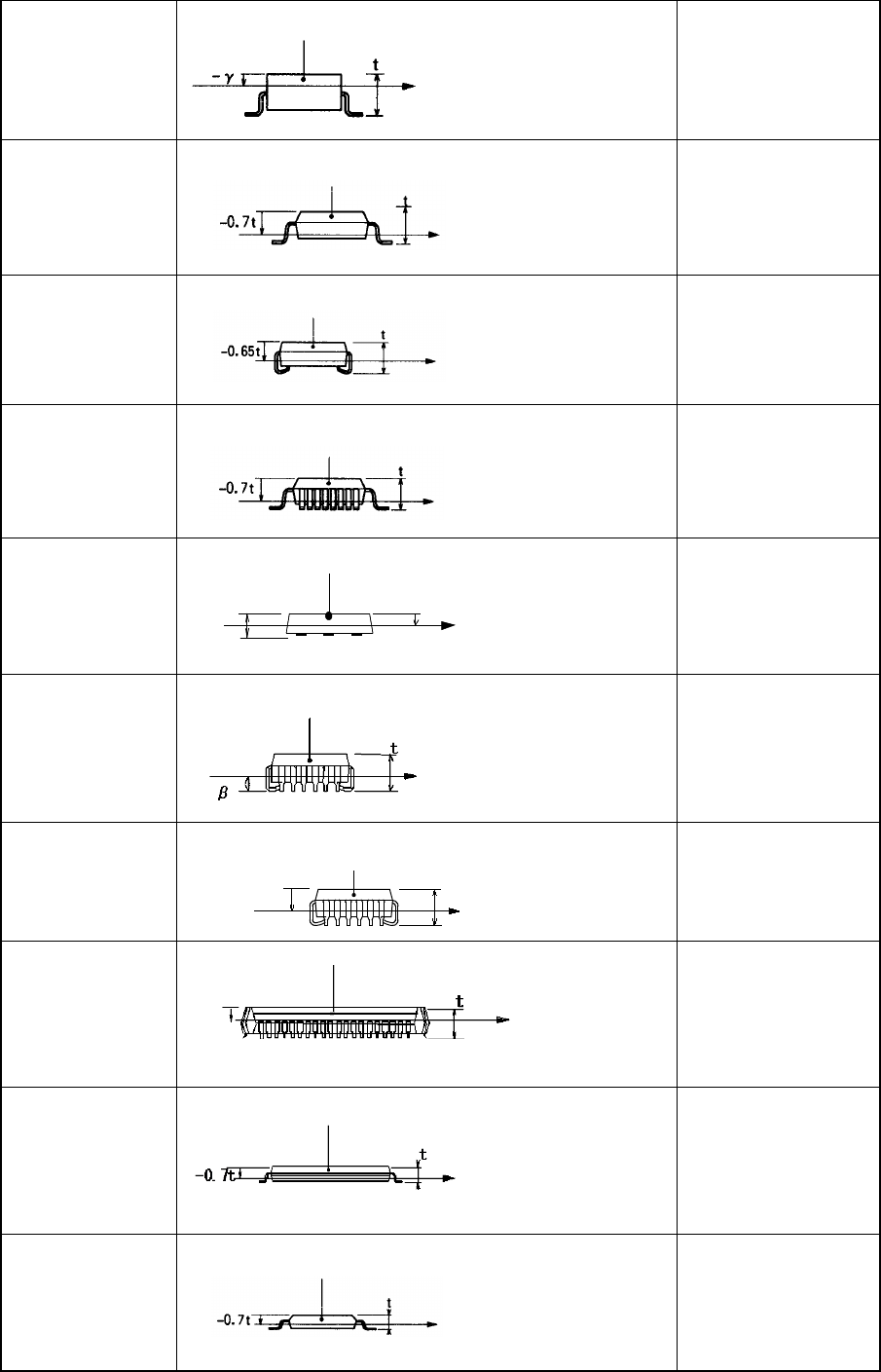
SOT
-γ
γ= 0.25
SOP
HSOP
-0.7×t
SOJ
-0.65×t
QFP
-0.7×t
QFN
t
-0.5t
-0.5×t
QFJ (PLCC)
※LNC60
-(t - β)
β = 0.4
QFJ(PLCC)
※FMLA
レーザ測定位置
モールド部
部品高さ
t
-0.65t
-0.65×t
PQFP (BQFP)
-0.45×t
TSOP
-0.7×t
TSOP 2
-0.7×t
Component height
Measurement
position with laser
Molding
Component height
Measurement
position with laser
Molding
Component height
Measurement position
with laser
Molding
Component height
Molding
Measurement
position with laser
Component height
Molding
Measurement position
with laser
Component
height
Measurement
position with laser
Molding
Component height
Measurement
position with laser
Molding
Molding
Component height
Measurement
position with laser
-0.45t
Measurement position
with laser
Molding
Component height
Measurement position
with laser
Molding
Compoent height

EPU Instruction Manual Chapter 4 Creating a Production Program
4-66
BGA
FBGA
-0.86×t
Network resistor
Same as that of the
square chip
Trimmer
- (t – 0.7)
Unidirectional lead
connector
Bidirectional lead
connector
Z-lead connector
-0.5×t
J-lead socket
0
Gull-wing socket
0
Socket with
bumper
0
Other components
-0.5×t
Note 1: If an angle error occurs when a square chip component such as a 0603 resistor is placed
on a board, change the value specified in the “Laser height” menu item on the “Expansion”
tab of the “Component” data screen to almost “-t/3 (default: -t/2), that is, toward the top
side of the component. It may improve the current condition.
Measurement
position with laser
Component height
Molding
Component height
Measurement
position with laser
Measurement
position with laser
Component height
Component height
Component height
Component height
Measurement
position with
laser
Measurement
position with
laser
Measurement
position with
laser
Component height
-0.5
Measurement
position with laser
Component height
Measurement
position with laser
Molding