JX-350_EPU使用说明书.pdf - 第137页
EPU Instruction M anual C hapter 4 Creating a Production Progr am 4- 89 (6 ) Pick posi t ion S pecif y the X, Y and Z coordinates of the c omponent pick - up position here. W hen you enter data into the “ Side ” and “ Po…
EPU Instruction Manual Chapter 4 Creating a Production Program
4-88
(4) Feeder type (You have to specify this menu item for a stick feeder, a tray or an
8-mm electric tape feeder.)
Select a type of a stick feeder, a tray or an 8-mm electric tape feeder.
However, the type set in the Component data is displayed here. To change it,
specify the desired type on the “Component” data screen.
For the a mechanical type, "M" is attached at the beginning of the name.
For an electric type, "E" is indicated at the beginning of the name.
• Tray holder
Tray holders are classified into "Type 1 (full specification)" and "Type 2 (half
specification)."
* For installing a tray holder, insert it so that the mounting marker can be localted at
the feeder mounting hole.
• For an 8-mm electric tape feeder:
When you select “8 mm paper” or “8 mm emboss” as an electric feeder on the
“Component” data screen, you can select “E 8mmS” (single lane) or “E 8mmD”
(double lane) in the “Feeder Type” field of the “Pick” data screen.
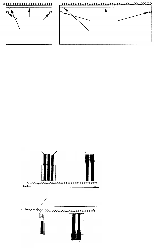
(5) Lane
Select a lane number for a stick feeder or an electric double tape feeder.
Lane numbers are seguentially assigned from the left with viewed from the front of the
machine regardless of which side a component is supplied from.
Lane
3 Lane 2 Lane 1 Lane 2 Lane 1
Lane 1 Lane 1 Lane 2
Feeder
mounting hole
Transport path
Butt
Butt
Mounting marker
type 2
Mounting marker
type 1
EPU Instruction Manual Chapter 4 Creating a Production Program
4-89
(6) Pick position
Specify the X, Y and Z coordinates of the component pick-up position here. When
you enter data into the “Side” and “Position” fields, the system automatically
calculates and displays these coordinates. Make fine adjustments of these
coordinates with teaching operation.
CAUTION
• To avoid a risk of injury, do not put your hands inside the machine
nor move your face or head close the machine while the system is
performing a teaching operation.
• If the feeder bank is never recognized (for example, immediately
after the devices of the machine return to their home positions or
the bank moves down then up), the head moves across the feeder
bank when you perform a teaching operation. Do not place your
hand or head in the machine, nor move your hand or face close to
the machine.
• When you use an HMS, use caution for preventing laser beam from
getting into your eyes directly or after reflecting by a mirror.
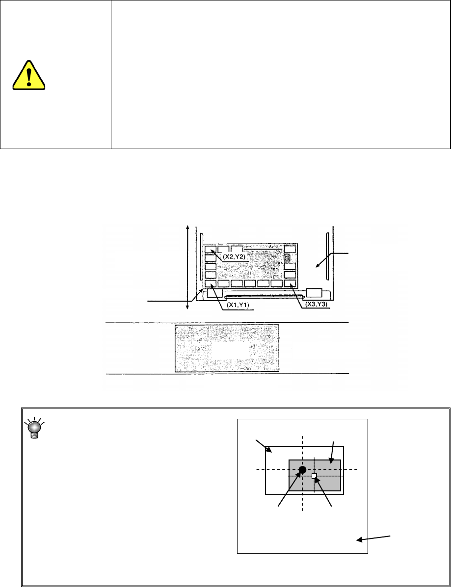
You can enter only the “X1” and “Y1” fields for a tape feeder, stick feeder or bulk
feeder. For a tray, you have to perform the teaching operation for three positions
(X1Y1, X2Y2 and X3Y3 as shown in the figure below) since the head moves to each
component position and pick up each one from a tray.
Specify the center of the frame
within which a component is
located instead of the center of a
component as the XY
coordinates.
* If you specify an incorrect value in the “X,” “Y” or “Z” field, a tombstone error or
pick-up error may tend to occur.
Frame
Component
Center of
the frame
Center of a
component
Feeder unit
Putting in/out
PWB
MTS, tray holder
Transport path
Machine front
Press the tray against here
EPU Instruction Manual Chapter 4 Creating a Production Program
4-90
(7) Status (Used)
Specify whether or not to use this feeder unit when production.
“Used” is selected as the initial setting.
(The “Yes” radio button is selected on the “Component List” screen. To change this
setting, press the [F2] key or click it with the right button of the mouse.)
If there are two or more feeder units, specify the unit that is actually used for
production with this machine.
A feeder unit whose “Status” is “Not used (No)” cannot be used as an alternate feeder
even though there are two or more feeder units.
(8) Remain
Specify the component remaining. It is necessary to specify the tray components,
but they can not specify the feeder components.