JX-350_EPU使用说明书.pdf - 第62页
EPU Instruction M anual C hapter 4 Creating a Production Progr am 4- 14 (10) PWB thickness Enter the thick ness of a PW B. The value you entered here is used to det ermine how much the system s hould move up the support …
EPU Instruction Manual Chapter 4 Creating a Production Program
4-13
* Restrictions on Longer sized PWB
- For a Longer sized PWB, optimization considering twice clamp (including optional
thrice clamp) cannot be executed if “Replacement with the optimization result” of the
optimization option is selected for optimization. Select “Order assigned from the
production program input order” for optimization.
- In the case of a circuit whose placing point bestrides two clamps (including optional
thrice clamp), set the bad mark position in the first placement area.
(8) Bad mark position
You do not have to enter this item for a single-plane PWB (setting is disabled).
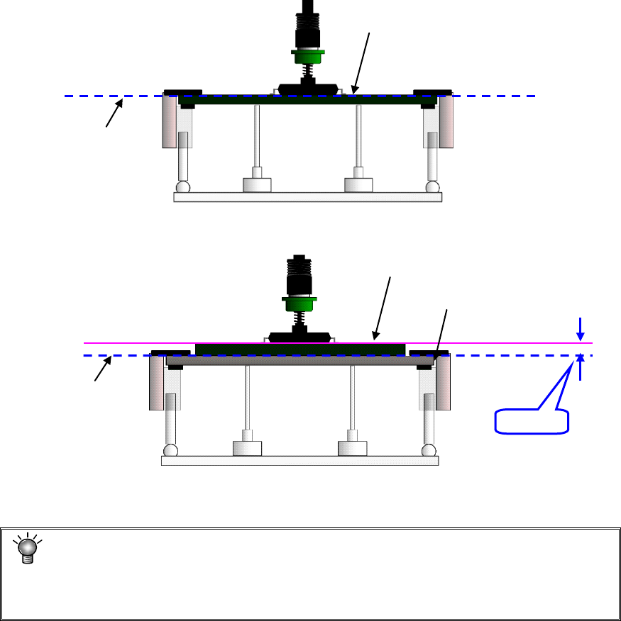
(9) PWB height
Enter the length of the top plane of the PWB from the transport reference plane
(reference height. This is the initial value (= 0.00) of the Z axis).
Usually, enter the initial value. When the transport reference plane is different in
height from the PWB top plane, enter the PWB height.
Example: Odd-shape PWBs or flexible PWBs are manufactured by piling the jig
(carrier board). In this case, enter “+t” for the PWB height.
• Normal case(Transport reference plane = PWB top plane height)
• Using the jig (Transport reference plane ≠ PWB top plane height)
If “+1” is not entered in this case, the component is pushed over the placement plane
(by the length of t) at placement, thereby damaging the component.
The nozzle height at component placement depends on the PWB height.
Accordingly if an incorrect value is set, the placement may lose uniformity. (The
component is released from a position remote to the PWB or the component is
pushed in too much in the PWB.)
+t
Transport reference plane
PWB top plane height
Jig (carrier board)
Transport reference plane
PWB top plane height
EPU Instruction Manual Chapter 4 Creating a Production Program
4-14
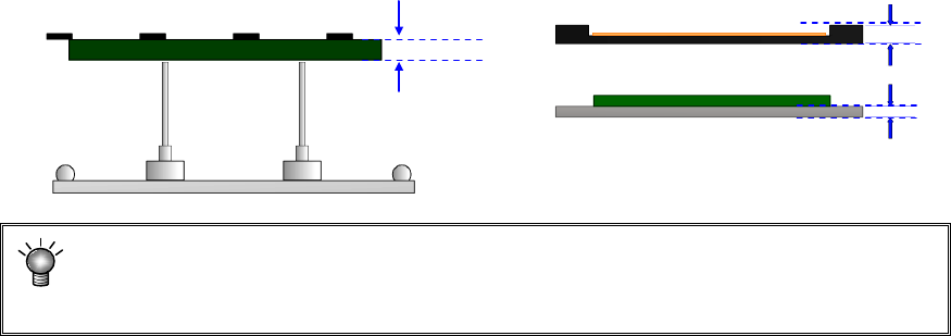
(10) PWB thickness
Enter the thickness of a PWB. The value you entered here is used to determine how
much the system should move up the support table when it is centering a PWB.
If an incorrect value is entered, the support pin pushes the PWB too much, thereby
damaging the PWB, and the placement may lose uniformity because the support pin
does not touch the PWB.
(11) Back height
Enter the height of the tallest component among the components placed on the back
side of a PWB (you have to enter a value that causes components on the back side
not to interfere with the support pin if components are placed on both sides of a
PWB).
* Not used in JX-350.
PWB thickness
EPU Instruction Manual Chapter 4 Creating a Production Program
4-15
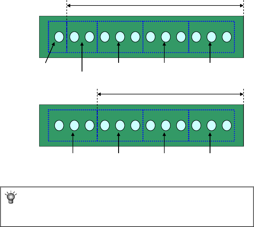
(12) Placement range every clamping
Enter a placement range at first clamp when clamping a large-shape PWB whose
PWB external size X exceeds 650 mm. When the number of components to be
placed is small, the tact may be improved by changing the placement range every
clamping.
[Three components can be picked up at once.]
Adjusting the placement range every clamping will reduce the pickup count from 5 to
4. This greatly improves the tact.
* For using a large-shaped PWB whose external length X exceeds 1200mm
(option):
If the placement range at first clamp is changed from 650 (mm), a PWB range that
cannot be placed may occur. So, do not change this placement range.
Placement range at first clamp: 650 mm (initial value)
#1 Pickup/
placement
#2 Pickup/
placement
#3 Pickup/
placement
#4 Pickup/
placement
#5 Pickup/
placement
#1 Pickup/
placement
#2 Pickup/
placement
#3 Pickup/
placement
#4 Pickup/
placement
Placement range at first clamp: 550 mm