JX-350_EPU使用说明书.pdf - 第114页
EPU Instruction M anual C hapter 4 Creating a Production Progr am 4- 66 BGA FBGA - 0.86 × t Networ k resistor Same as that of the square chip T rimmer - (t – 0.7) Unidirectional lead connector Bidirectional lead connecto…
EPU Instruction Manual Chapter 4 Creating a Production Program
4-65
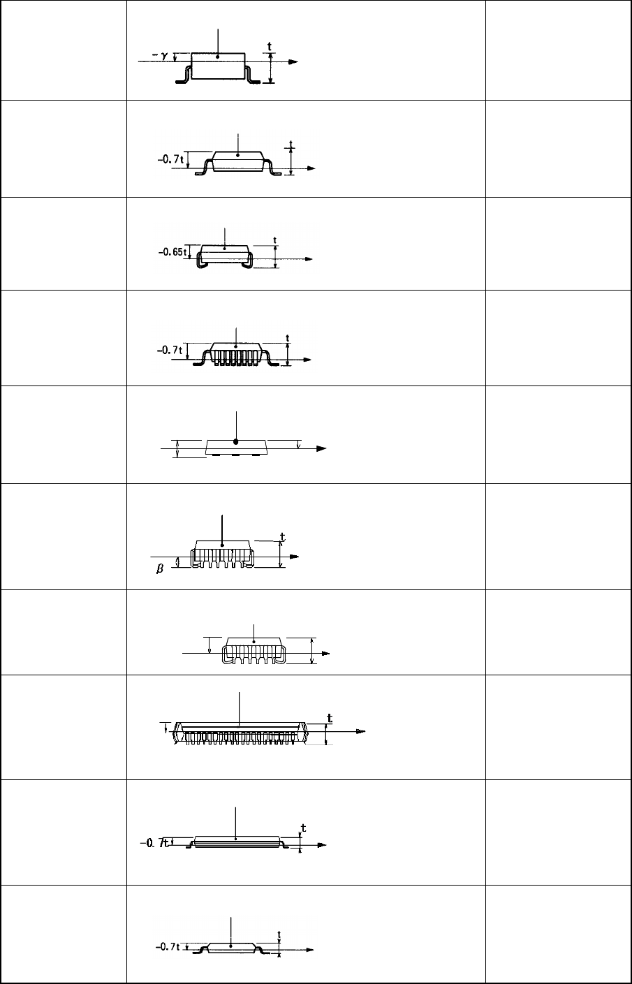
SOT
-γ
γ= 0.25
SOP
HSOP
-0.7×t
SOJ
-0.65×t
QFP
-0.7×t
QFN
t
-0.5t
-0.5×t
QFJ (PLCC)
※LNC60
-(t - β)
β = 0.4
QFJ(PLCC)
※FMLA
レーザ測定位置
モールド部
部品高さ
t
-0.65t
-0.65×t
PQFP (BQFP)
-0.45×t
TSOP
-0.7×t
TSOP 2
-0.7×t
Component height
Measurement
position with laser
Molding
Component height
Measurement
position with laser
Molding
Component height
Measurement position
with laser
Molding
Component height
Molding
Measurement
position with laser
Component height
Molding
Measurement position
with laser
Component
height
Measurement
position with laser
Molding
Component height
Measurement
position with laser
Molding
Molding
Component height
Measurement
position with laser
-0.45t
Measurement position
with laser
Molding
Component height
Measurement position
with laser
Molding
Compoent height

EPU Instruction Manual Chapter 4 Creating a Production Program
4-66
BGA
FBGA
-0.86×t
Network resistor
Same as that of the
square chip
Trimmer
- (t – 0.7)
Unidirectional lead
connector
Bidirectional lead
connector
Z-lead connector
-0.5×t
J-lead socket
0
Gull-wing socket
0
Socket with
bumper
0
Other components
-0.5×t
Note 1: If an angle error occurs when a square chip component such as a 0603 resistor is placed
on a board, change the value specified in the “Laser height” menu item on the “Expansion”
tab of the “Component” data screen to almost “-t/3 (default: -t/2), that is, toward the top
side of the component. It may improve the current condition.
Measurement
position with laser
Component height
Molding
Component height
Measurement
position with laser
Measurement
position with laser
Component height
Component height
Component height
Component height
Measurement
position with
laser
Measurement
position with
laser
Measurement
position with
laser
Component height
-0.5
Measurement
position with laser
Component height
Measurement
position with laser
Molding
EPU Instruction Manual Chapter 4 Creating a Production Program
4-67
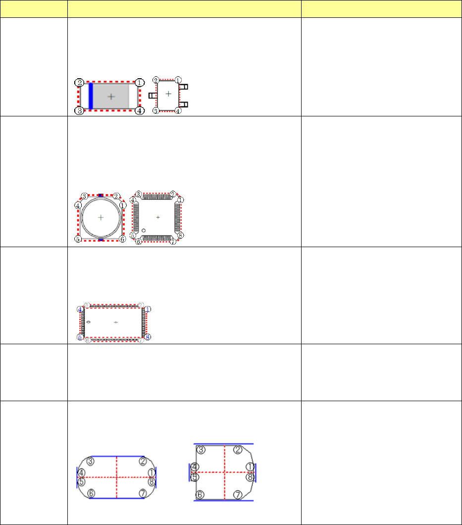
(4) Comp Shape
You can specify the shape of a component to be recognized with laser. The main
applicable components are described in the table below.
Comp Shape
Operation Applicable components
Corner
Square
The system detects four vertexes from the
measurement data and calculates/corrects a
positioning error and/or an angle error to place a
component on a board.
Select this shape for a component whose shape is
similar with a rectangle/square without any notch.
Chip, Melf, SOT, QFN, trimmer,
unidirectional connector,
bi-directional connector, Z-lead
connector and other components
Corner cut
The system detects five to eight vertexes from the
measurement data and calculates/corrects a
positioning error and/or an angle error to place a
component on a board.
Select this shape for a component that has at least one
notch or a component whose lead is located at a
position to be measured with laser such as a QFP.
Aluminum electrolytic capacitor,
GaAsFET, SOP, HSOP, SOJ, QFP,
FQFP (BQFP), TSOP, TSOP2, BGA,
network resistor, J-lead socket,
unidirectional connector, gull-wing
PLCC socket and socket with a
bumper
PLCC
The system detects eight vertexes form the
measurement data, and uses four of them to
calculate/correct a positioning error and/or an angle
error and place a component on a board. This setting
is exclusively for a PLCC.
PLCC
Cylinder
The system calculates/corrects a positioning error at
the pick-up angle set in the measurement data to place
a component on a board.
Select this setting for a component
that has no vertex such as a
cylindrical component. In this case,
the angle is ignored (the polarity is
ignored), and only the center of a
component is obtained.
Flexible
The system extracts a total of 8 measurement data
near positions of smallest component width in the X/Y
direction and calculates/corrects angle offset and then
mounts components.
Flexible is used for components that
result in laser recognition error 93
(shape recognition error) for the
reason of "No missing edge" and
"Missing edge" of polygonal
components, or "PLCC"
Because the number of data to be
used is smaller than other
component shapes, the accuracy is
lower but more types of components
can be measured.