JX-350_EPU使用说明书.pdf - 第175页
EPU Instruction M anual C hapter 4 Creating a Production Progr am 4- 127 • Example of the [ Matrix Copy ] comm and result Component I D X Y Angle Component nam e R1 5.00 10.00 45.00 1608 -A R2 10.00 10.00 0.00 1608 -A No…
EPU Instruction Manual Chapter 4 Creating a Production Program
4-126
(14) Update Pick Offset
The component pick-up coordinates set on the “Pick” data screen are reflected in the
“Picking offset XYZ” field on the “Component” data screen.
When you select one data record on the “Pick” data edit screen after teaching, and
the [Update Pick Offset] command on the “Edit” menu, the difference between the
default pick-up value of the selected “Pick data” and the taught result can be
reflected in the “Picking offset” of the “Component data.”
(15) Mark copy
* Not used in JX-350.
(16) Mark Paste
* Not used in JX-350.
(17) Mark database
* Not used in JX-350.
(18) Matrix Copy
This command copies data in the range selected with the [Cut] or [Copy] command to
the specified position.
* This command cannot be selected when you use the sort function.
1) Placement data
This command inserts data in the range selected with the [Cut] or [Copy] command
before the cursor position.
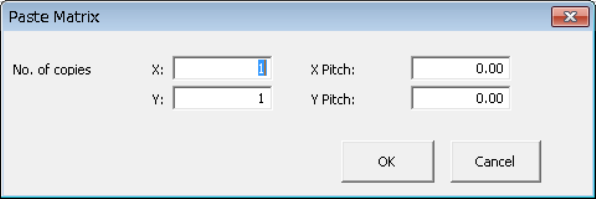
When you specify the “X” and “Y” fields of “No. of copies,” and “X Pitch” and “Y
Pitch” fields, the system allows you to copy the data in a matrix with adding or
subtracting the entered value to/from the component placement position in the X
direction and that in the Y direction.
After you execute the [Matrix Copy] command, all of the component IDs are
changed to “#.”
① No. of copies, X: Specify the number of times the system will copy data in the
X direction.
② No. of copies, Y: Specify the number of times the system will copy data in the
Y direction.
③ X Pitch: Specify the amount to increment or decrement the
component placement or pick-up position in the X direction.
④ Y Pitch: Specify the amount to increment or decrement the
component placement or pick-up position in the Y direction.
⑤ OK: This button pastes the data.
⑥ Cancel: This button cancels the paste operation.
EPU Instruction Manual Chapter 4 Creating a Production Program
4-127
• Example of the [Matrix Copy] command result
Component ID X Y Angle Component name
R1 5.00 10.00 45.00 1608-A
R2 10.00 10.00 0.00 1608-A
No. of copies X 3 X Pitch: 0.50
No. of copies Y 1 Y Pitch: 1.00
R1 5.00 10.00 45.00 1608-A
R1 10.00 10.00 0.00 1608-A
# 5.50 10.00 45.00 1608-A
# 10.50 10.00 0.00 1608-A
# 6.00 10.00 45.00 1608-A
# 11.00 10.00 0.00 1608-A
# 6.50 10.00 45.00 1608-A
# 11.50 10.00 0.00 1608-A
# 5.00 11.00 45.00 1608-A
# 10.00 11.00 0.00 1608-A
# 5.50 11.00 45.00 1608-A
# 10.50 11.00 0.00 1608-A
# 6.00 11.00 45.00 1608-A
# 11.00 11.00 0.00 1608-A
# 6.50 11.00 45.00 1608-A
# 11.50 11.00 0.00 1608-A
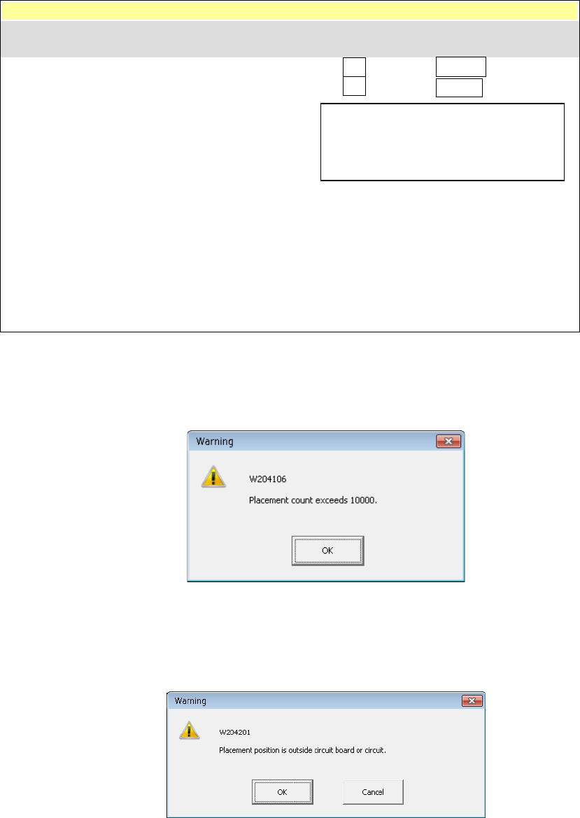
In the following cases, an error occurs and the system displays the corresponding
error message.
① The number of data records you entered exceeds the maximum number of
records.
• OK: This button cancels the copy operation. No data is copied.
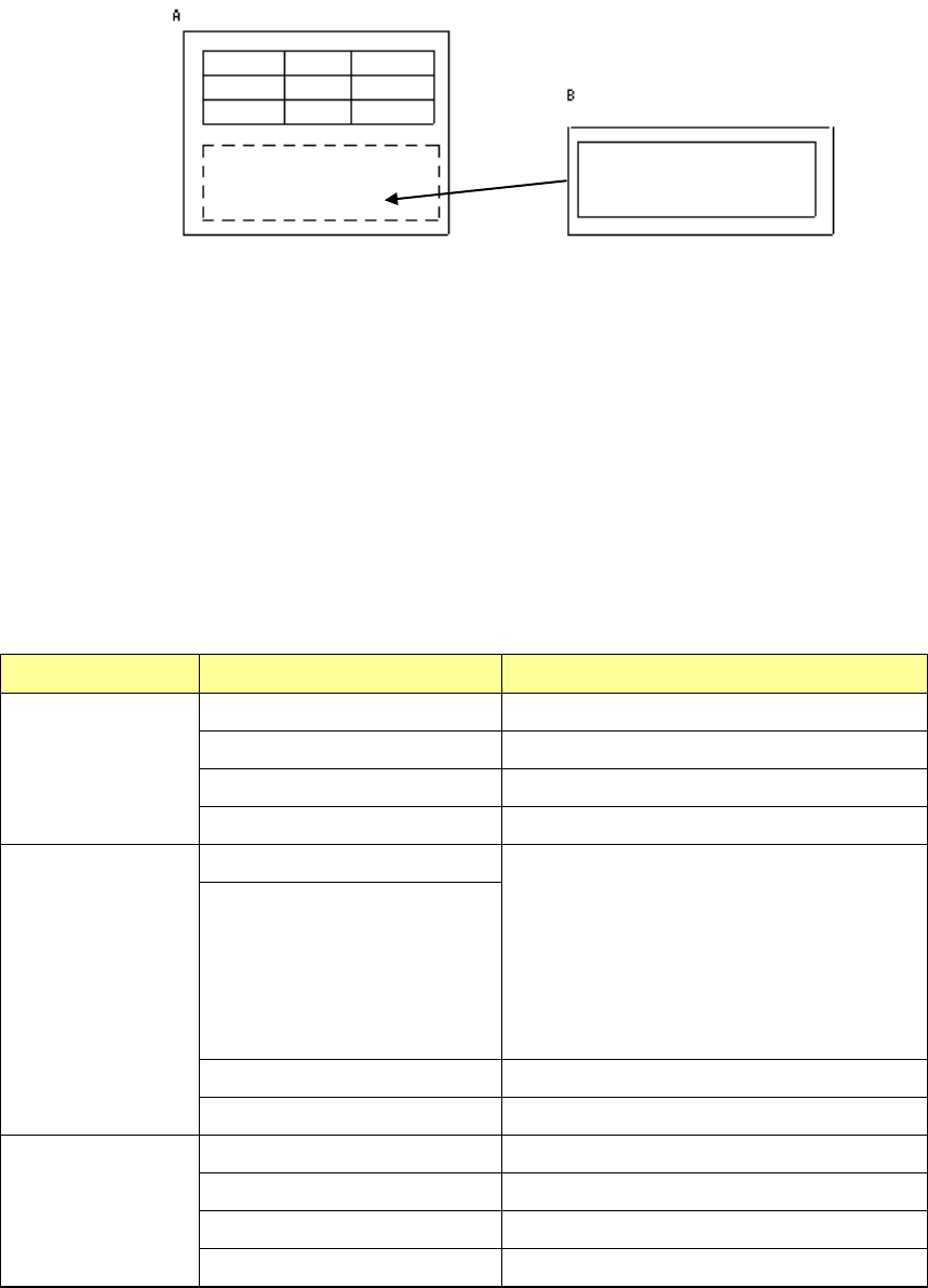
② The component placement position is outside a PWB or circuit.
• OK: This button continues copying data. However, the range over mark is
appended to the error data record.
• Cancel: This button cancels the copy operation.
− The copied block is inserted above the
specified line.
− All of the Component IDs are set to “#”.
Component ID X Y Angle Component name
EPU Instruction Manual Chapter 4 Creating a Production Program
4-128
(19) Production program copy
This command uses the copy function to combine two or more production programs.
If any area fiducial mark is used in Placement data of the production program to be
copied (“B” in the figure above), BOC marks of PWB data of the program “B” are
handled as area fiducial marks.
<How to copy>
① Load a source production program used as the reference. (In the figure above, it is
the PWB A.)
② Specify (load) a destination production program in which a circuit is copied. (In the
figure above, it is the PWB B.)
③ Specify the differences (offset X, Y and θ) between the PWB origin of the source
production program and that of the destination production program.
④ Perform a matrix copy function.
Source PWB Destination PWB Result
Single-plane PWB Single-plane PWB Single-plane PWB
Multi-plane matrix PWB Single-plane PWB
Multi-plane non-matrix PWB Single-plane PWB
Two or more reference circuits Single-plane PWB
Multi-plane matrix
PWB
Single-plane PWB Single-plane (circuit) or Multi-plane (circuit)
matrix PWB
When the number of divisions is equal to the
pitch between the consecutive circuits, and
the offset theta is 0 or 180 degrees, the PWB
is copied as a multi-plane matrix PWB.
*1
Multi-plane matrix PWB
Multi-plane non-matrix PWB Single-plane PWB
Two or more reference circuits Single-plane PWB
Multi-plane
non-matrix PWB
Single-plane PWB Single-plane PWB
Multi-plane matrix PWB Single-plane PWB
Multi-plane non-matrix PWB Single-plane PWB
Two or more reference circuits Single-plane PWB
*1: If a PWB can be copied as a multi-plane matrix PWB, the system displays the
“Question” dialog box that asks you if you want to copy a PWB as a single-plane
PWB or a multi-plane matrix PWB.
If two or more circuits are overlapped with each other, the system also displays the
“Question” dialog box that asks you if you want to copy a PWB as a single-plane
PWB or a multi-plane matrix PWB.