JX-350_EPU使用说明书.pdf - 第131页
EPU Instruction M anual C hapter 4 Creating a Production Progr am 4- 83 * Reg arding the data of the “I nspection ” and “I nspection 2 ” tabs, the entr y may be restrict ed depending on set ting such as t he component ty…
EPU Instruction Manual Chapter 4 Creating a Production Program
4-82
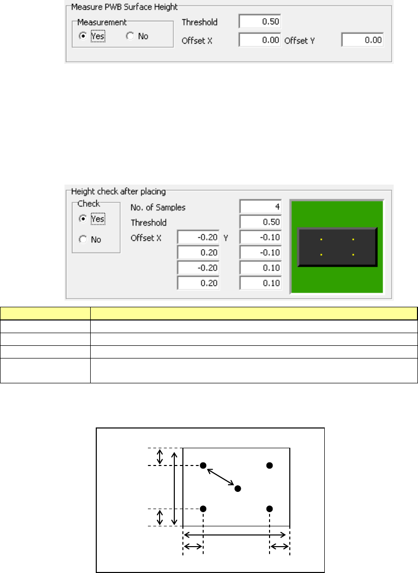
(2) Measure PWB Surface Height
This setting item allows the system to measure the height of the board surface at the
component placement position to correct the Z-coordinate of the component
placement position.
The center (one point) of the component placement position is to be measured.
According to the measurement result, enter the threshold value for determining
whether the board warps or not in the “Threshold” field.
When the measurement result is within the range of – “Threshold value” to “Threshold
value,” the system determines that a component can be placed on the board.
To measure a position other than the component placement position, enter the “Offset
X” and “Offset Y” fields.
(3) Check Component Height after place
This setting item allows the system to measure the heights of four corners of a
component such as one having a boss after it is placed on a board, and check to see
if the placed component is tilted or not.
When the measurement result is within the range of – “Threshold value” to “Threshold
value,” the system determines that the component has been placed on the board
normally.
If it exceeds this range, the current production stops temporarily.
Setting item
Description
Check
Specify whether to check or not by selecting the corresponding radio button.
No. of Samples
Specify how many positions to be checked within the range of 2 to 4.
Threshold
Specify a value for determining whether a placed component is tilted or not.
Offset X, Y
Specify where to check by entering the offset from the component placement
position. From the top, specify the measurement positions 1, 2, 3 and 4.
The relation between the measurement offset positions and the check positions is
shown in the figure below.
Offset value
30% of the
vertical length
Measuring
position 1
Measuring
position 3
Measuring
position 2
Measuring
position 4
30% of the
horizontal length
30% of the
vertical length
30% of the
horizontal length

EPU Instruction Manual Chapter 4 Creating a Production Program
4-83
* Regarding the data of the “Inspection” and “Inspection 2” tabs, the entry may be
restricted depending on setting such as the component type.
Component type Tombstone
Dimension
check
SOT
Angle
Pick
Position
Detection
Measure
PWB
Surface
Height
Check
Component
Height after
place
Square chip
○
○
×
○
○
○
Square chip (LED)
○
○
×
○
○
○
MELF
○
○
×
○
○
○
Aluminum electrolytic
capacitor
○ ○ × ○ ○ ○
SOT
○
○
○
○
○
○
Trimmer
○
○
×
○
○
○
Network resistor
○
○
×
○
○
○
SOP
○
○
×
○
○
○
HSOP
○
○
×
○
○
○
SOJ
○
○
×
○
○
○
QFP
○
○
×
○
○
○
GaAsFET
○
○
×
○
○
○
PLCC (QFJ)
○
○
×
○
○
○
PQFP (BQFP)
○
○
×
○
○
○
TSOP
○
○
×
○
○
○
TSOP2
○
○
×
○
○
○
BGA
○
○
×
○
○
○
QFN
○
○
×
○
○
○
Unidirectional lead
connector
○ ○ × ○ ○ ○
Bidirectional lead
connector
○ ○ × ○ ○ ○
Z-lead connector
○
○
×
○
○
○
J-lead socket
○
○
×
○
○
○
Gull-wing socket
○
○
×
○
○
○
Socket with bumper
○
○
×
○
○
○
Other components
○
○
×
○
○
○
4.1.4.2.8 Option
* JX-350 is not applicable to the opyion.
4.1.4.2.9 Vision data
* JX-350 is not applicable to the version data.
EPU Instruction Manual Chapter 4 Creating a Production Program
4-84
4.1.5 Pick data
This “Pick” data screen allows you to specify where a component is supplied and where it
is picked up.
The component feed units provided in the feeder bank are a tape feeder, stick feeder,
bulk feeder, and tray holder. The other component feed unit is MTS.
Additionally, there are two kinds of feeder banks, mechanical feeder bank and electric
feeder bank. The mechanical feeder bank uses the mechanical feeder while the electric
feeder bank uses the electric feeder.
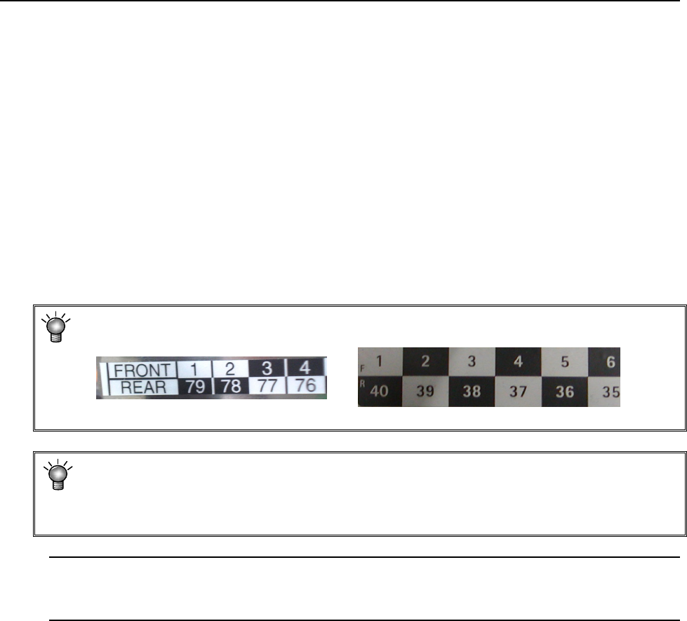
For the mechanical feeder bank, there are 79 holes in one feeder bank intended to set the
feeder. The number of a hole, into which the pin at the top end of the feeder is inserted,
becomes the feeder number assigned to the feeder.
For the electric feeder bank, there are 40 rails on one feeder bank.
The number of a rail, onto which the feeder is mounted, becomes the number assigned to
the pick data.
* In the feeder bank, numbers are expressed in 2 upper and lower rows.
On the front side, the upper-row numbers are those for feeder settings.
<Mechanical feeder bank> <Electric bank>
* The component pick-up position is automatically assigned with the Optimization
function, but you have to manually assign the pick-up position in the following cases
• when the feeder layout is fixed, or
• when you change the feeder layout after optimization.
Note: If you load a production program file created with another model, the system may
recalculate the component pick-up coordinates set as the Pick data mainly because
the reference coordinates vary depending on the model.