JX-350_EPU使用说明书.pdf - 第150页
EPU Instruction M anual C hapter 4 Creating a Production Progr am 4- 102 (4) M odel option ① Consider the component t ypes and heights W hen you check t his check box, the system specif ies the com ponent layer with cons…
EPU Instruction Manual Chapter 4 Creating a Production Program
4-101
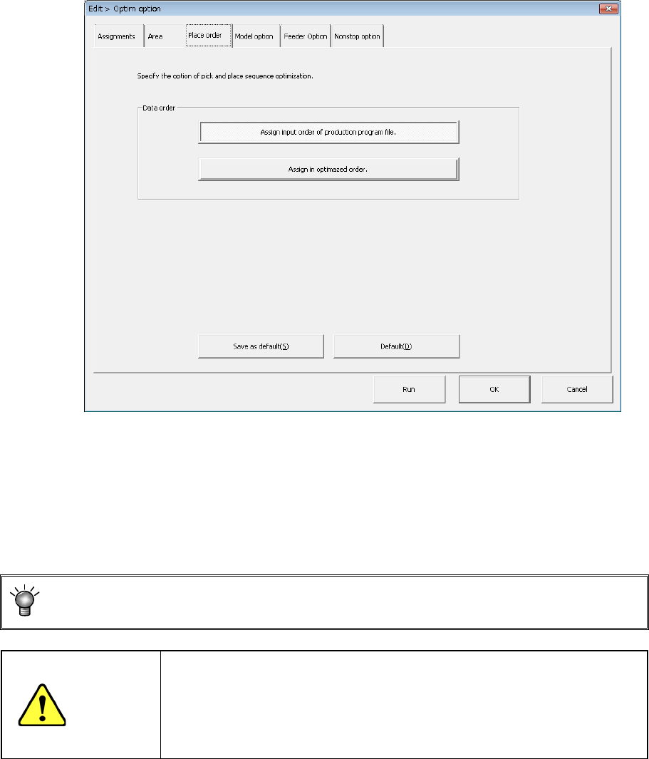
(3) "Placement order" option
Specifies the option to be used for changing the component placement order.
1) Data order
a) Assign in input order of Production Program File
Placement data will be displayed in entry order (that is, not changed at all).
b) Assign in optimized order
Placement data will be displayed in the optimization order.
You can display the optimized order of placement order by selecting the
[Optimization]/[Divided Placement Data] commands from the menu bar also.
CAUTION
"Assign in optimized order" is a function for editing the optimized data
(optimization result can be referred to, but cannot be edited).
However, once this function is executed, the data in order of the
original date entry will be deleted. Therefore, backup the data
before executing this function.
EPU Instruction Manual Chapter 4 Creating a Production Program
4-102
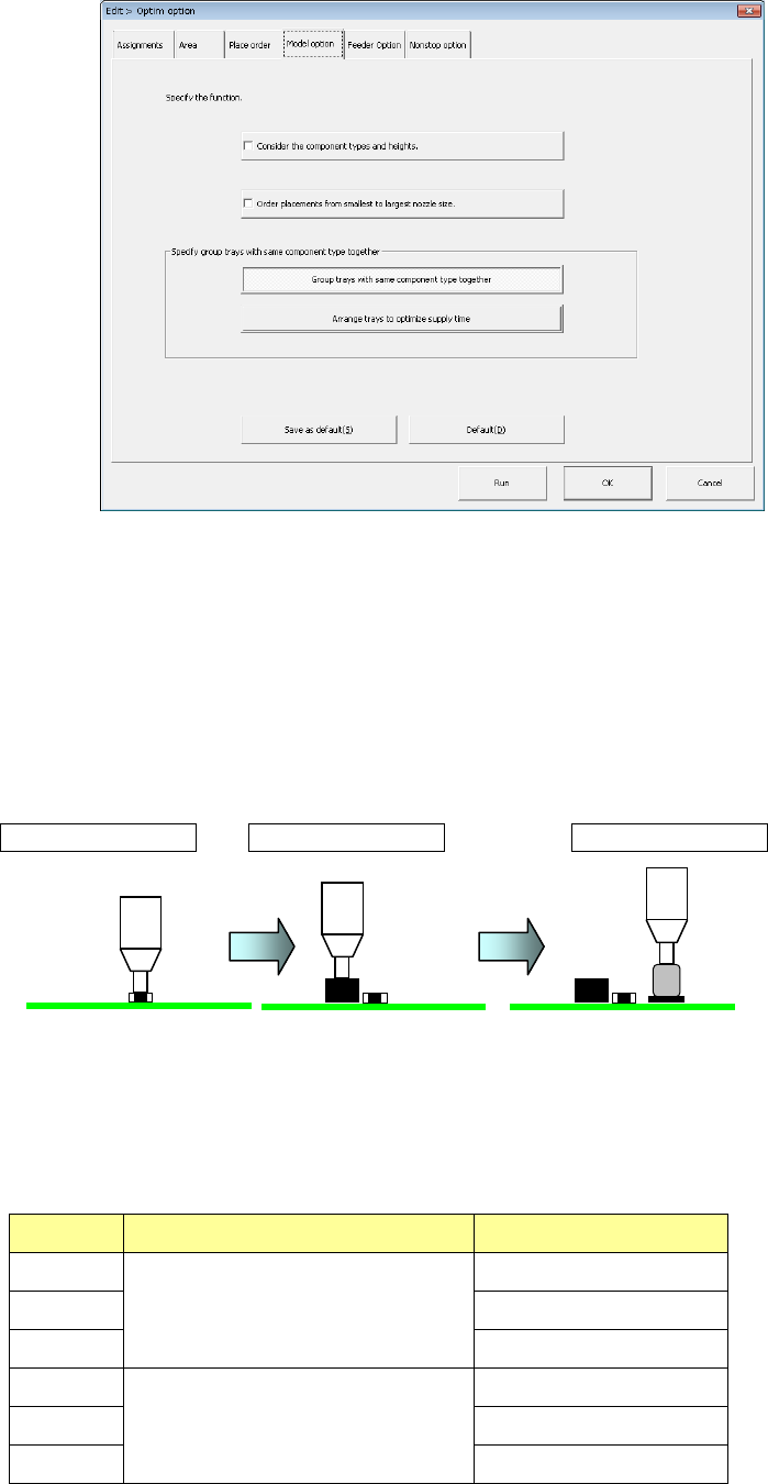
(4) Model option
① Consider the component types and heights
When you check this check box, the system specifies the component layer with
considering the component height automatically to create a program that places
components in high density (that is, places components adjacently).
When you check this check box actually, the system places components in the
following order:
<Component placement by considering the component type and component height>
Placement order ① Placement order ② Placement order ③
<Relation between the component placement priority and the component type and
height>
As indicated with “Priority” in the table below, components other than aluminum
electrolytic capacitor is prioritized.
Priority Component type Component height (mm
1
Components other than aluminum
electrolytic capacitor
0 < t ≦ 5.5
2 5.5 < t ≦ 12.0
3 12.0 < t
4
Aluminum electrolytic capacitor
0 < t ≦ 5.5
5 5.5 < t ≦ 12.0
6 12.0 < t
EPU Instruction Manual Chapter 4 Creating a Production Program
4-103
<Priority of layers>
The relation between layers is shown in the table below.
Priority Layer type
1 Placement layer
2 Component layer
3 Component type/height layer
The system skips a component to continue the current PWB production if it cannot
place it on a board due to a component run-out error during PWB production when you
do not select the option “Stop system on components run out” on the “Production
(Pause)” tab of the “Operation option” menu. The system places the skipped
component finally after the production resumes by your replenishing the feeder that
caused a component run-out error. At this point, the production conditions based on
the component height may not be satisfied. Therefore, we recommend that you select
the option “Stop system on component run out” on the Operation option menu when
you select “Consider the component types and heights.”
2) Order placement from smallest to largest nozzle size:
When this item is checked off, components of the small-diameter nozzle are first
placed at optimization.
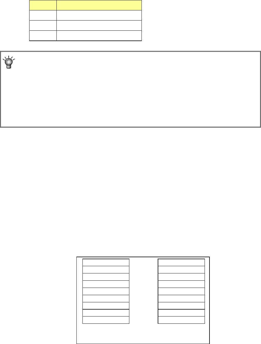
3) Same tray centralized layout specification
Regarding the same type tray components to be supplied to the MTS, specify
whether to arrange trays collectively or arrange them giving priority to the feed
speed.
• Same tray concentrated layout: Trays are arranged for each sane
component type.
• Feed speed priority layout: Trays are arranged by giving priority to
the feed speed.
Comp Type A
A
A
Comp Type B
B
B
Comp Type C
C
C
Comp Type A
Comp Type B
Comp Type C
A
B
C
A
B
C
When “Group trays with same
component type together” is selected
When “Arrange trays to optimize
supply time” is selected