JX-350_EPU使用说明书.pdf - 第125页
EPU Instruction M anual C hapter 4 Creating a Production Progr am 4- 77 Note 1: Ent er the distance f rom the center posit ion of a component centered with laser to the coordinat es of the component placem ent position i…

EPU Instruction Manual Chapter 4 Creating a Production Program
4-76
Example 2: Taking the following component as an example, enter the offset value. The
unit of numerical value is "mm (millimeter)."
( (no color) ⇒ Lead section, (colored) ⇒ Mold section, (bold line) ⇒ Pad)
Since the coordinates of the component placement position are different from the
center position of the component centered with laser, the system will not place a
component at the correct position. Therefore, enter this difference into the “Place
Offset” field as the offset value.
If any offset is not entered, components will be placed as shown below.
In this case, enter an offset value so that the tip of the lead will come on the center of
the pad.
If "X = -5.5, Y = -10" is entered in the "Place Offset" field, components will be placed
as shown below.
Coordinates of the component placement position
Laser height
Pad on a PWB
Top view of a component
Lateral view of a component
(from the front)
Center position of a component centered with laser
3
5.5
1
2
2
5
5
2
EPU Instruction Manual Chapter 4 Creating a Production Program
4-77
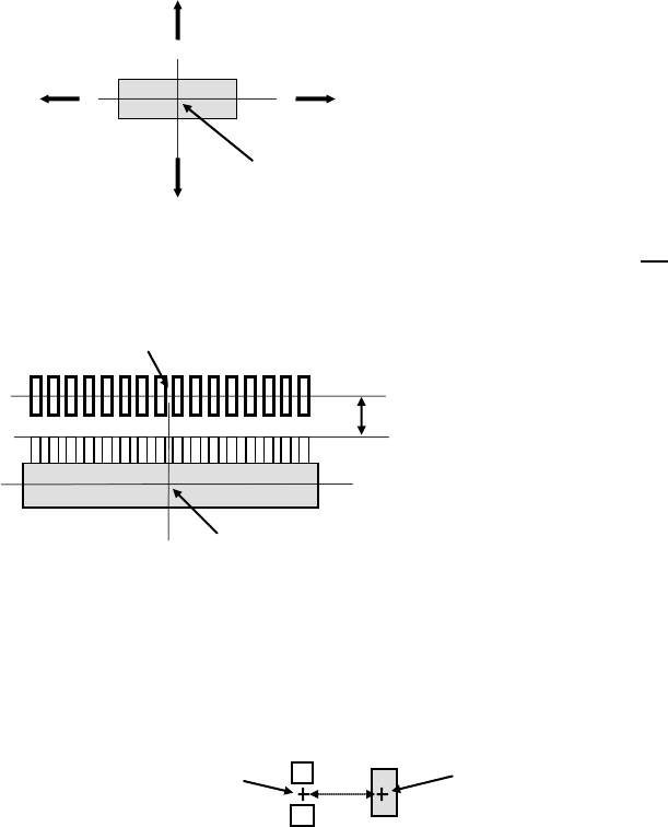
Note 1: Enter the distance from the center position of a component centered with laser
to the coordinates of the component placement position in the “Place Offset”
field. For the sign of the value, see the figure below (the arrow mark means the
distance to the coordinates of the component placement position).
Example: To place a component as shown below, enter "X = 0, Y = +3" into the "Place
Offset" field.
Note 2: Enter the offset value with regarding the placement angle as "0".
Example: If the placement angle of a component is "90," enter the "Place Offset" field by
assuming the placement angle to be "0." In the case shown below (placement
angle of "90"), enter "X = 0, Y = 2."
Note 3: To enter an offset value, we have two methods: One is to enter the offset value
into the "Place Offset" field on the "Component" screen and the other is to add or
subtract the offset value to or from "X" and "Y" fields on the "Placement" screen.
For entry of placement data, however, an offset value must be adjusted one by
one for each placement position. Therefore, in the case of placing components
of the same type on a number of positions, or if you do not want to change the
placement data, then enter the offset value in the "Place Offset" field on the
"Component" screen.
Note 4: If you change a value in the “Laser position” field of some components on the
“Centering” tab of the “Component” data screen, the center position of the
component centered with laser may be changed. Therefore, you may be able to
adjust the component placement position by changing the value in the “Laser
position” field without entering any value in the “Place Offset” field. However, in
this case, you have to set the “Laser position” field so that the system can center
a component stably.
Center position of a component
centered with laser
Coordinates points of the component placement position
3
Center position of a component
centered with laser
−Y
+Y
+X
−X
2
Coordinates of the component
placement position
Center position of a component
centered with laser
EPU Instruction Manual Chapter 4 Creating a Production Program
4-78
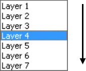
(3) Component layer
The “Component layer” field specifies the priority of each component on the same
placement layer.
This selection is effective only if the system produces a PWB in the optimized order.
Note that this selection does not cause the system to be put in the pause state due to
a component run-out error unlike the selection of the “Layer” field on the “Placement”
data screen.
Select the layers from 1 (highest priority) to 7 (lowest priority) from the pull-down list.
(4) Speed
When a small nozzle is used to pick up components or when a vacuum leakage
occurs from a groove on the top surface of the component, the acceleration of the
XYZ axis can be changed from the default value.
• XY
From the drop-down list, select the speed that the XY-axes accelerate until they
move to the component placement position after they pick up a component (in 10
steps).
• Place Z down
From the drop-down list, select the speed that the Z-axis accelerates (to adjust the
stress imposed on a component) when it moves down at the component
placement position.
• Place Z up
From the drop-down list, select the speed that the Z-axis accelerates (to adjust the
stress imposed on a component) when it moves up at the component placement
position.
• Theta (Measure)
Specify the theta rotation speed by the drop-down list.
In the status where the head is provided with a component, the specified speed is
valid for all operations.
This value sets the speed that the theta axis accelerates when a component is
recognized with laser.
• Theta (Other)
Specify the theta rotation speed by the drop-down list.
This speed is effective for all rotation operations except for a rotation for
measurement operation with laser when a head holds a component.
This value sets the speed that the theta axis accelerates when a component is not
recognized with laser.
(5) Tw o-step speed control
Specify whether to control the speed at which the nozzle moves up and down in two
steps when a component is placed on a board.
When you select the “Yes” radio button in the “Adjust” field, enter the height to be
controlled in two steps for moving up and moving down a nozzle respectively.
Place first.
Place later.