JX-350_EPU使用说明书.pdf - 第190页
EPU Instruction M anual C hapter 4 Creating a Production Progr am 4- 142 No. Menu item Description 1 Feeder Position Shows the component supply position. W hen a stick feeder or an 8 - mm electric double tape feeder is u…
EPU Instruction Manual Chapter 4 Creating a Production Program
4-141
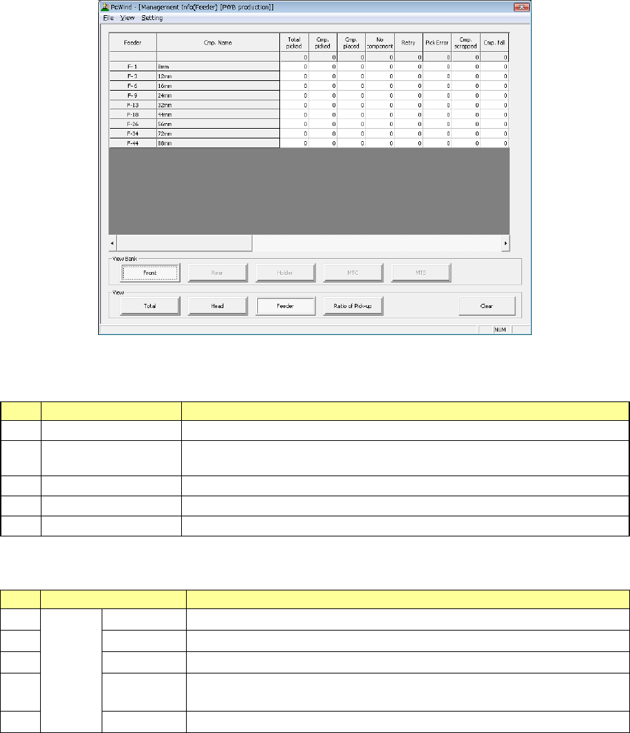
3) Management Info (Feeder)
The production management information per feeder is displayed.
When you select “Front” as the “View Bank,” the following screen appears.
“View Bank” allows you to select a bank on which a component is located to be displayed in the list
of the screen.
No.
Menu item
Description
1
Front
Shows only components set on the front bank.
2 Rear Shows only components set on the rear bank. (When the rear feeder option is
available.)
3
Holder
Not used in JX-350.
4 MTC Not used in JX-350.
5
MTS
Shows only components set on the MTS.
“View” allows you to change the displayed management information.
No.
Menu item
Description
1
View
Total
Shows the total management information.
2 Head Shows the production management information per head.
3
Feeder
Shows the production management information per feeder.
4 Pick Sorts the component pick-up rates at each component supplied position and
shows them.
5
Clear
Clears the production management information.

EPU Instruction Manual Chapter 4 Creating a Production Program
4-142
No.
Menu item
Description
1 Feeder Position
Shows the component supply position.
When a stick feeder or an 8-mm electric double tape feeder is used, its lane
number is shown in parentheses.
2 Cmp. Name Shows the name of a component to be supplied.
3 Total picked
Shows how many times the component supply unit picked up a component.
(“Cmp. picked” + “Pick Error”)
4 Cmp. picked
Shows the number of components that were picked up with the component
supply unit successfully.
5 Cmp. placed
Shows the number of components that were picked from the component
supply unit and then placed on boards.
6 Cmp. scrapped
Shows the number of components that were lost at feeders.
If the value set in the menu item “Retry” of the Component data is changed,
the machine cannot calculate the number of the lost components correctly.
You have to clear the production management information in such a case.
Number of lost components = “Total Picked” – “Retry” × (value set in the
menu item “Retry” of the Component data + 1) – “Cmp. placed”
7 Pick Error
Number of times the machine failed to pick up a component from the
corresponding feeder.
8 No component
Shows how many times components have run out on the component supply
unit.
When a feeder is used, this indicates the same thing as the menu item
“Retry” below. When you set the number of remaining components, this
shows how may times the “Number of retry over errors” + “Number of
remaining components” became “0.”
9 Retry
Shows how many times a retry over error occurred at the component supply
unit.
(The system picks up components the number of times set in the “Retry” field
on the “Component” data screen. If the system cannot pick up a
component, the value in this field increments by 1.)
10 LA Recog.
Number of times a laser recognition retry over error occurred at the
corresponding feeder.
11 Vision Recog. Not used in JX-350.
12 Lead Not used in JX-350.
13 Irregular dimensions
Shows how many times the system detected an irregularly shaped
component.
14 Vrfy/Sot Shows how many times the system judged an SOT error.
15 Tombstone
Shows how many times the system judged that a component picked up from
the component supply unit stood on its side.
16 Copla Error Not used in JX-350.
17 Other error
Number of times any other errors such as drop of a component were judged
to occur.
• The total number of each item is displayed on the second line of the screen.
EPU Instruction Manual Chapter 4 Creating a Production Program
4-143
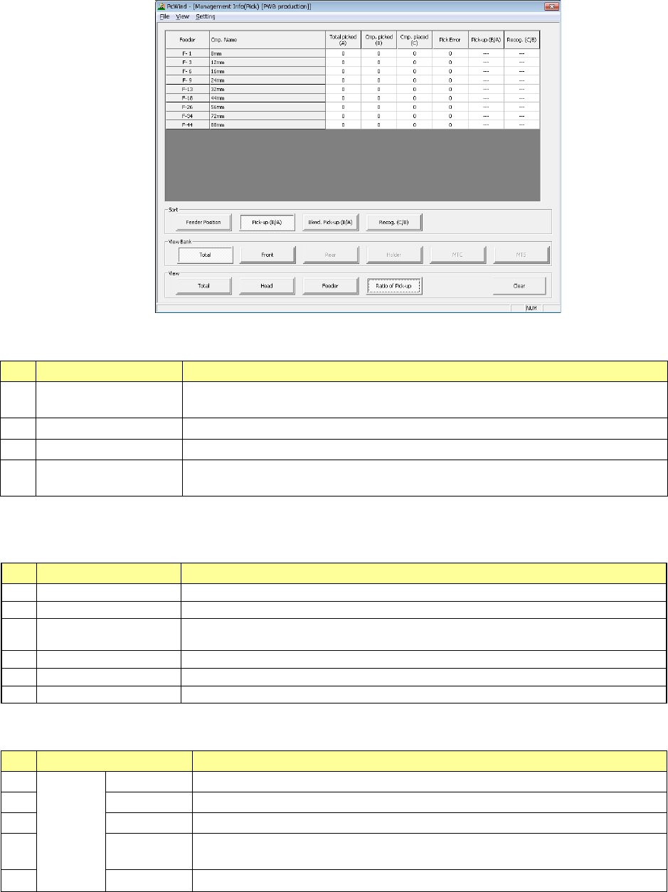
4) Management Info (Pick)
The system shows “the pick-up ratio per component supply position (Pick-up ratio =
Number of pick-ups / (Number of pick-ups + Number of pick-up errors))” on the
screen.
♦ The pick-up ratios are normally displayed on the screen in the order of ascending
pick-up ratios.
“Sort”: Select how to sort the pick-up ratios displayed in the list.
No.
Menu item
Description
1 Feeder Position↓
Sorts the pick-up ratios in the order of descending feeder positions to display
them.
2
Pick-up (B/A)
↓
Sorts the pick-up ratios in the order of ascending pick-up ratios to display them.
3
Bkwd. Pick-up (B/A)
↑
Sorts the pick-up ratios in the order of descending pick-up ratios to display them.
4 Recog. (C/B)↓
Sorts the pick-up ratios in the order of ascending recognition ratios to display
them.
“View Bank” allows you to select a bank on which a component is located to be displayed in the list
of the screen.
No.
Menu item
Description
1
Total
Shows all components set on the front and rear banks.
2
Front
Shows only components set on the front bank.
3
Rear
Shows only components set on the rear bank. (When the rear feeder option is
available.)
4
Holder
Not used in JX-350.
5
MTC
Not used in JX-350.
6
MTS
Shows only components set on the MTS.
“View” allows you to change the displayed management information.
No.
Menu item
Description
1
View
Total
Shows the total management information.
2
Head
Shows the production management information per head.
3
Feeder
Shows the production management information per feeder.
4 Pick Sorts the component pick-up rates at each component supplied position and
shows them.
5
Clear
Clears the production management information.