88192277-01-19 - Micron Technical Reference V9 Volume 4.pdf - 第130页
SENSORS INDUCTIVE SENSORS 40.8 Technical Reference Manual Chapter Issue 6, May 19 INDUCTIVE SENSORS Description An inductive sensor consists of an in duction loop which generates a magn etic field. When a metal object is…
SENSORS
ULTRASONIC SENSOR
Chapter Issue 6, May 19 Technical Reference Manual 40.7
ULTRASONIC SENSOR
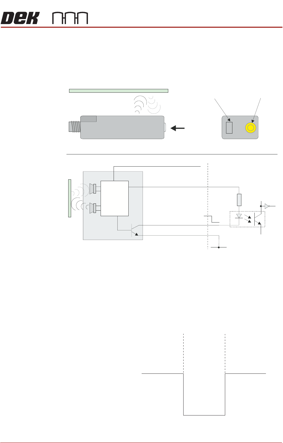
Description The ultrasonic sensor transmits a conical shaped area of ultrasonic sound
waves; some of the waves are rebounded back to the receiver in the sensor.
When a board passes over the sensor the amount of rebounded sound
changes, switching the output of the sensor.
Figure 40-9 Ultrasonic Sensor
Testing Procedure If the sensor fails to operate carry out the following:
1. Disconnect the sensor.
2. Short out the signal to 0V on the socket.
3. Check the relevant digital input under Diagnostics - System - Display all
Digital Inputs to confirm, or otherwise, that the sensor is defective.
Figure 40-10 Voltage Diagram
+V
Opto-isolator
1K8
0V
Pin 1 12V
Pin 2 Teach
Pin 3 0V
Pin 4 Signal
+V
0V
View on Arrow A
Bi-Colour Status LED
Teach Button
Ultrasonic Sensor
A
Digital Input
Control
Circuit
Board
Absent
Present
Absent
12V
0V
Signal
SENSORS
INDUCTIVE SENSORS
40.8 Technical Reference Manual Chapter Issue 6, May 19
INDUCTIVE SENSORS
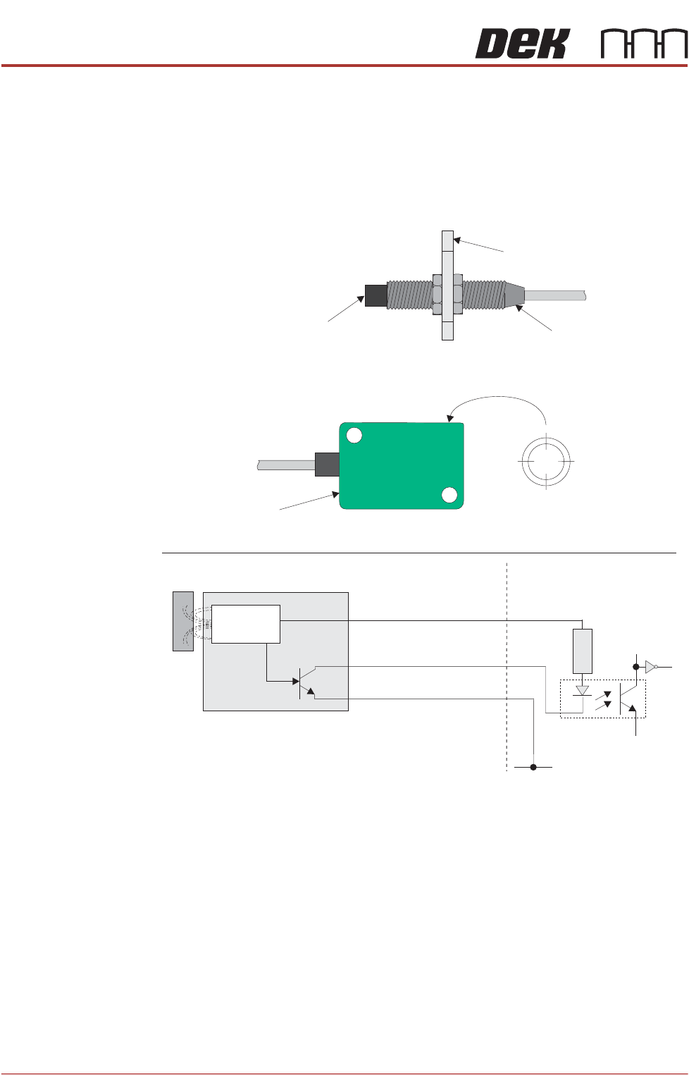
Description An inductive sensor consists of an induction loop which generates a magnetic
field. When a metal object is moved close (typically 3 - 4mm) to the sensing area
of the sensor, the inductance of the loop changes, increasing the current flow
through the loop. This change is detected by internal circuitry and switches the
sensor.
Figure 40-11 Inductive Sensor
Testing/
Adjustment
The Squeegee/ProFlow home sensor can be tested using Diagnostics. The
sensor incorporates an LED indicating the status of the sensor. There is no
adjustment for this sensor as it is in a fixed position.
For testing and adjustment of the rail lifted sensor, refer to the relevant transport
rail chapter.
Squeegee/ProFlow Home Sensor
Rail Lifted Sensor
Sensing Area
(Range 3mm)
Sensing Area
(Range 4mm)
Sensor Bracket
+V
Opto-isolator
1K8
0V
12V Brown
0V Blue
Signal Black
Control
Circuit
Digital Input
LED
LED
SENSORS
CAPACITIVE PROXIMITY SENSOR
Chapter Issue 6, May 19 Technical Reference Manual 40.9
CAPACITIVE PROXIMITY SENSOR
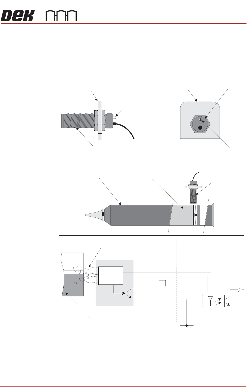
Description A capacitive proximity sensor consists of an RC oscillator which emits a
frequency field. When the target, in this case the solder paste, moves away
from the sensing range (ie paste low), the capacitance increase effectively
changes the internal current which is detected by an adjustable trigger. The
control circuit switches the output transistor on.
Figure 40-12 Capacitive Proximity Sensor
Capacitive Proximity Switch
Sensor Bracket
LED
Paste Level Sensor
LED Adjuster
and Indicator
Sensor Bracket
Sensor
PastePaste Cartridge
Paste Level
Sensor
+V
Opto-isolator
1K8
0V
0V
12V
RC Frequency Field
Solder Paste
12V
0V
Pin 1
Control
Circuit
Pin 2
Pin 3
Digital Input