88192277-01-19 - Micron Technical Reference V9 Volume 4.pdf - 第215页
TRANSPORTATION - MAJOR RELOCATION TRANSIT BRACKETS AND SCREWS REMOVAL Chapter Issue 5, Nov 19 Technical Reference Manual 42.49 TRANSIT BRACKETS AND SCREWS REMOV AL NOTE All transit brackets and screws must be removed fro…
TRANSPORTATION - MAJOR RELOCATION
MACHINE SUPPLIES AND ENVIRONMENTAL CONDITIONS
42.48 Technical Reference Manual Chapter Issue 5, Nov 19
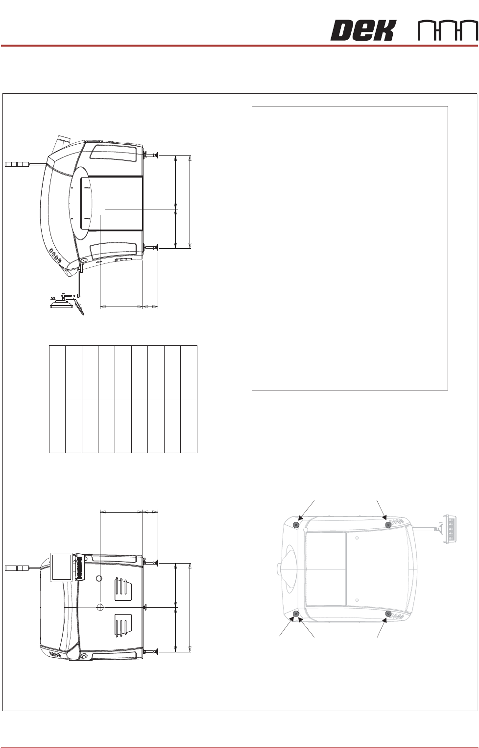
Centre of Gravity and Seismic Anchorage
Figure 42-16 Type 1 Covers (Only)
Side View (right)
CG
L2
a
b
h
L1
Front View
CG
L3
d
b
h
c
Centre of Gravity
a
b
c
d
h
L1
L2
L3
1150mm
130mm
1106mm
530mm
485mm
565mm
665mm
541mm
Plan View
Centre of Gravity
Seismic Anchorage
Machine Feet
(in 4 positions)
Min = -100kg
Max = +400kg
Min = -100kg
Max = +400kg
Min = -100kg
Max = +400kg
Min = -100kg
Max = +400kg
Seismic Anchorage
The calculations for the downward and upward force of the feet
is calculated in line with the 1
997 Uniform Building Code and
SEMI S2-0703. Results indicate that under worse circumstances
(calculation for hazardous fluids) an upward lifting force has to be
expected and it is strongly recommended to secure the machine
directly to the floor.
NOTE
In the figure on the left, negative
numbers are upward loads and
positive
numbers are downward
loads.
Appropriate attachment points may be fitted to the front and rear
of the machine base frame. For more information, contact DEK
Printing Machines.
Alternatively, the supplied machine feet can be replaced with feet
incorporating holes allowing the feet to be secured directly to the floor.
Additional seismic calculations must be undertaken for the floor and
any anchor points that are used.
The length of the machine feet (measurement in the figures above)b
must not exceed 130mm to meet seismic anchorage calculations.
TRANSPORTATION - MAJOR RELOCATION
TRANSIT BRACKETS AND SCREWS REMOVAL
Chapter Issue 5, Nov 19 Technical Reference Manual 42.49
TRANSIT BRACKETS AND SCREWS REMOVAL
NOTE
All transit brackets and screws must be removed from the machine before
power is applied. Machine damage may occur if transit brackets or screws are
not removed prior to power up. Transit brackets and screws are red in colour for
easy identification.
To remove the transit brackets and screws from the machine, remove/open the
rear printhead cover. On Type 1 cover machines, remove the two upper side
panels as detailed in the Covers chapter.
Transit Brackets The transit brackets include the following:
• Front Transit Bracket
• Rear Transit Bracket
• Rear Chase Transit Bracket
• Cover Frame Transit Bracket (For printers with Anti Vibration (AV) mounts
fitted to the covers frame)
The following procedure must be adhered to and care must be taken to ensure
that the chase/ASM is released in a controlled manner to prevent damage to
the roller bearings or the actuators.
NOTE
In the following procedure, the numbers in brackets refer to the Front and Rear
Transit Brackets, Rear Chase Transit Bracket, Cover Frame Transit Bracket
figures.
To remove the chase transit brackets, carry out the following procedure:
1. Using a 13mm spanner, loosen the four M8 nuts (3) directly below the front
and rear transit brackets (2), Chase Transit Brackets figure refers.
2. Slowly loosen the four M8 nuts (3) above the front and rear transit brackets
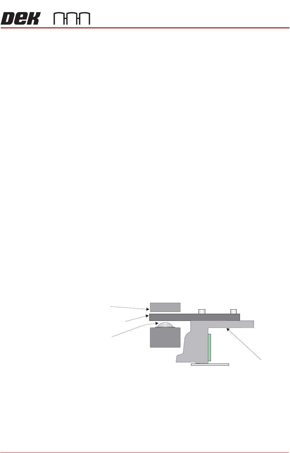
(2) to lower the roller counter plates onto the rollers bearings.
3. Using a 4mm Allen key, remove the M5 cap head screws (9) and washers
(10) that attach the adaptor bracket (8) at each end of the front and rear
transit brackets (2) to the left and right printheads.
4. Remove the four M8 nuts (3) and washers (4) above the front and rear transit
brackets (2).
5. Remove the front and rear transit brackets (2) from the M8 chase studs (1).
6. Loosen the transit adjustment screw lock nut (6) on the front and rear transit
brackets (2).
Chase
Chase Clamp
Roller Bearing
Roller Counter Plate
TRANSPORTATION - MAJOR RELOCATION
TRANSIT BRACKETS AND SCREWS REMOVAL
42.50 Technical Reference Manual Chapter Issue 5, Nov 19
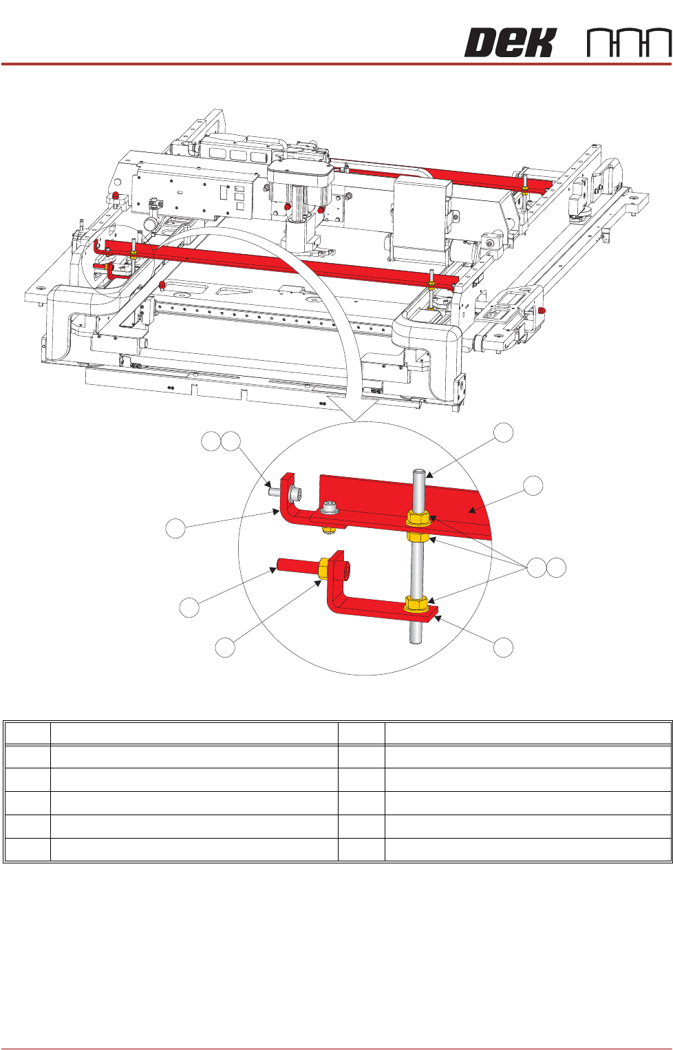
Figure 42-17 Front and Rear Transit Brackets
NOTE
Item 5, the Left Chase Bracket is fitted upside down on dual lane machines.
Item Description Item Description
1 M8 Chase Stud 6 Transit Adjustment Screw Lock Nut
2 Front/Rear Transit Bracket 7 Transit Adjustment Screw
3 M8 Nut 8 Adaptor Bracket
4 M8 Washer 9 M5 Cap Head Screw
5 Left Chase Transit Bracket 10 M5 Washer
9
1
2
3
4
5
6
7
8
10