88192277-01-19 - Micron Technical Reference V9 Volume 4.pdf - 第200页
TRANSPORTATION - MAJOR RELOCATION TRANSPORTING THE MACHINE 42.34 Technical Reference Manual Chapter Issue 5, Nov 19 2. Loosen (all the way) the M24 half nut and full nut on all four machine legs. Figure 42-6 T ype 1, 2, …
TRANSPORTATION - MAJOR RELOCATION
TRANSPORTING THE MACHINE
Chapter Issue 5, Nov 19 Technical Reference Manual 42.33
TRANSPORTING THE MACHINE
If the machine is to be relocated to another site it is recommended that it is
encased in its original transportation box, or if not available, a new transporta-
tion box can be obtained from ASM Assembly Systems Weymouth Ltd.
If the machine is to be transported by sea freight, packing advice should be
sought from specialist freight companies.
WARNING
MACHINE LIFTING. TO PREVENT SERIOUS INJURY TO PERSONNEL, DURING
LIFTING AND TRANSPORTATION OPERATIONS, ENSURE THE MACHINE IS
LIFTED AND TRANSPORTED IN ACCORDANCE WITH INSTRUCTIONS DETAILED
IN THIS SECTION.
NOTE
Damage to the machine will occur if the machine is lifted:
• Using lifting strops
OR . . .
• From the sides
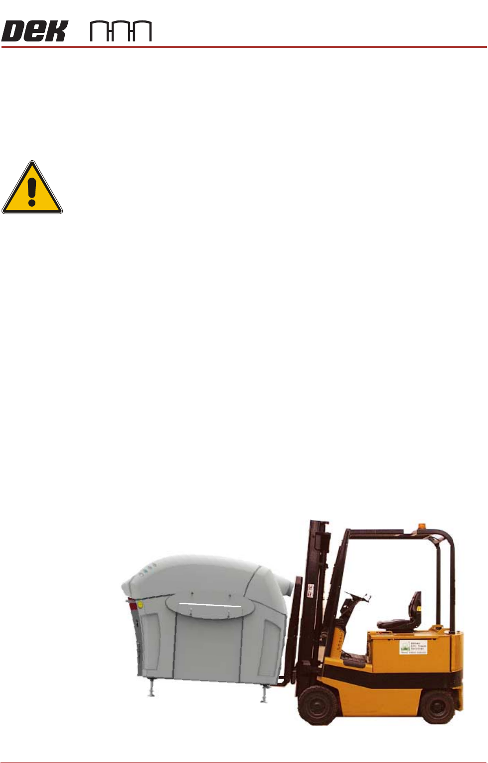
ASM recommends that the machine is lifted from the rear at all times however,
the machine may be lifted from the front if the machine is to be moved a short
distance or moved into line.
The machine may be lifted using a forklift truck or similar machine that meets
the following criteria:
• Minimum fork length of 1372mm (54 inches)
• Fork span >686mm (27 inches) and <914mm (36 inches)
• Fork Height (thickness) <50mm (2 inches)
• Lifting capability of 2000kg
1. Locate the forks under the machine base and lift the machine.
TRANSPORTATION - MAJOR RELOCATION
TRANSPORTING THE MACHINE
42.34 Technical Reference Manual Chapter Issue 5, Nov 19
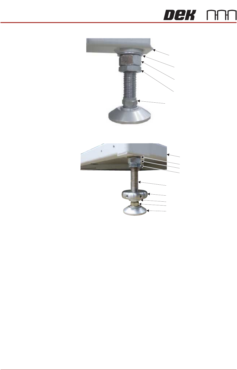
2. Loosen (all the way) the M24 half nut and full nut on all four machine legs.
Figure 42-6 Type 1, 2, 3 & 5 machines
Figure 42-7 Type 4 machine
3. Screw the legs into the machine, leaving room for a bracket to fit between
the two nuts.
4. Place the machine on the base of the transportation box.
5. Remove the forklift.
6. Wrap the machine to prevent damage to the panels.
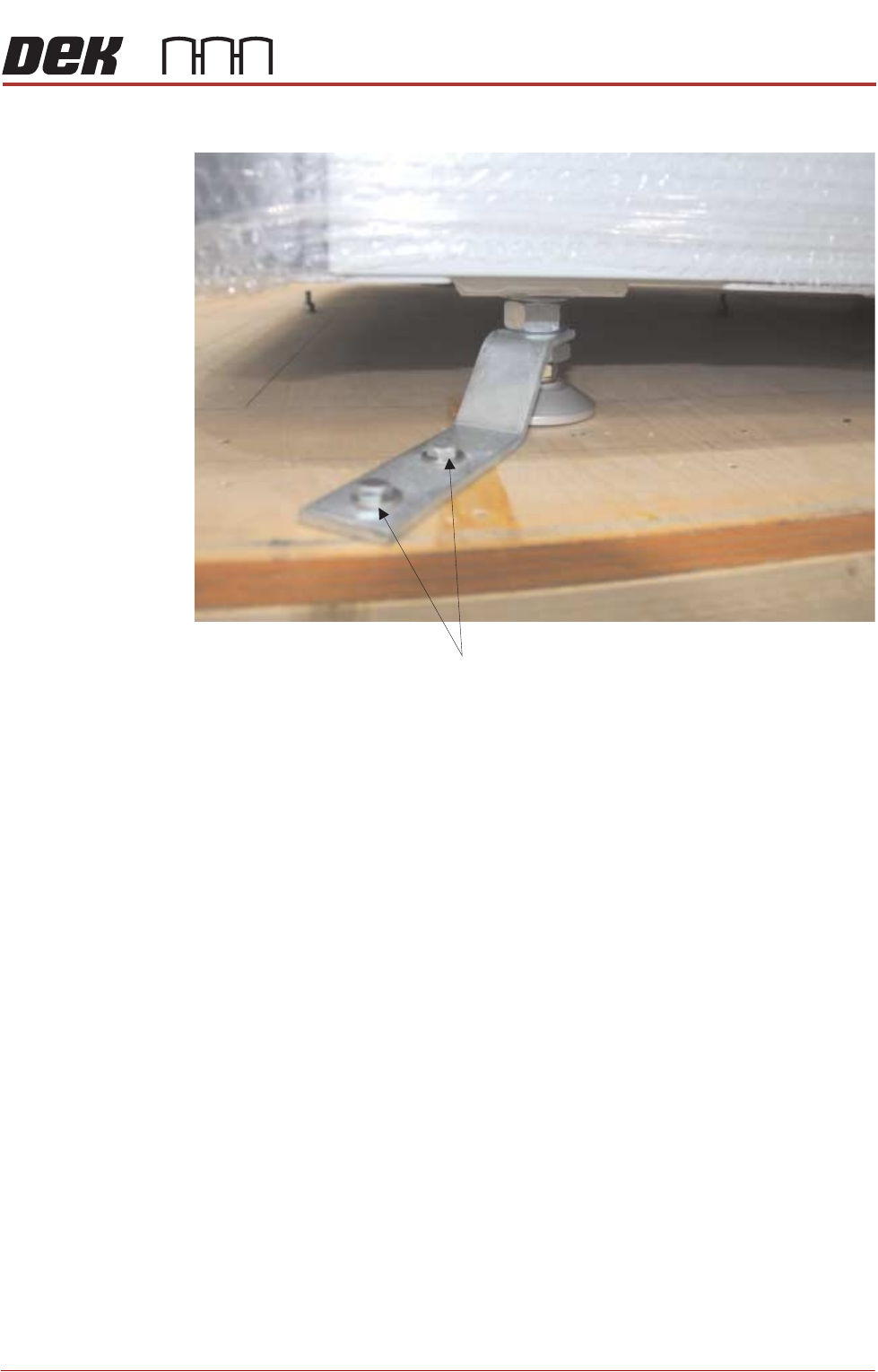
7. The printer is secured to the base of the transportation box with four brackets
each held in place using two M8 hex head woodscrews. Fit all four brackets
M24 Washer
Machine Frame
M24 Full Nut
M24 Half Nut
Leg Adjusting Nut
Washer
Machine Frame
M24 Full Nut
Half Nut
Locating Collar
Leg Bolt
Foot
Half Nut
Leg Adjusting Nut
TRANSPORTATION - MAJOR RELOCATION
TRANSPORTING THE MACHINE
Chapter Issue 5, Nov 19 Technical Reference Manual 42.35
ensuring the bracket fits between the two nuts.
8. Tighten the M24 half nut and full nut against the bracket.
9. Secure three sides of the transportation box with screws.
10. Wrap the loose items and pack securely inside the box.
11. Fit the fourth side panel and lid of the transportation box with screws.
12. The machine is now ready for transportation to its new location.
M 8 x 60 Woodscrews