88192277-01-19 - Micron Technical Reference V9 Volume 4.pdf - 第149页
TRANSPORTATION - MINOR RELOCATION TRANSIT BRACKET INSTALLATION Chapter Issue 4, May 19 Technical Reference Manual 41.7 7. T ighten the nylon screws (5 ) on to the carriage rail.
TRANSPORTATION - MINOR RELOCATION
TRANSIT BRACKET INSTALLATION
41.6 Technical Reference Manual Chapter Issue 4, May 19
Cover Frame
Transit Bracket
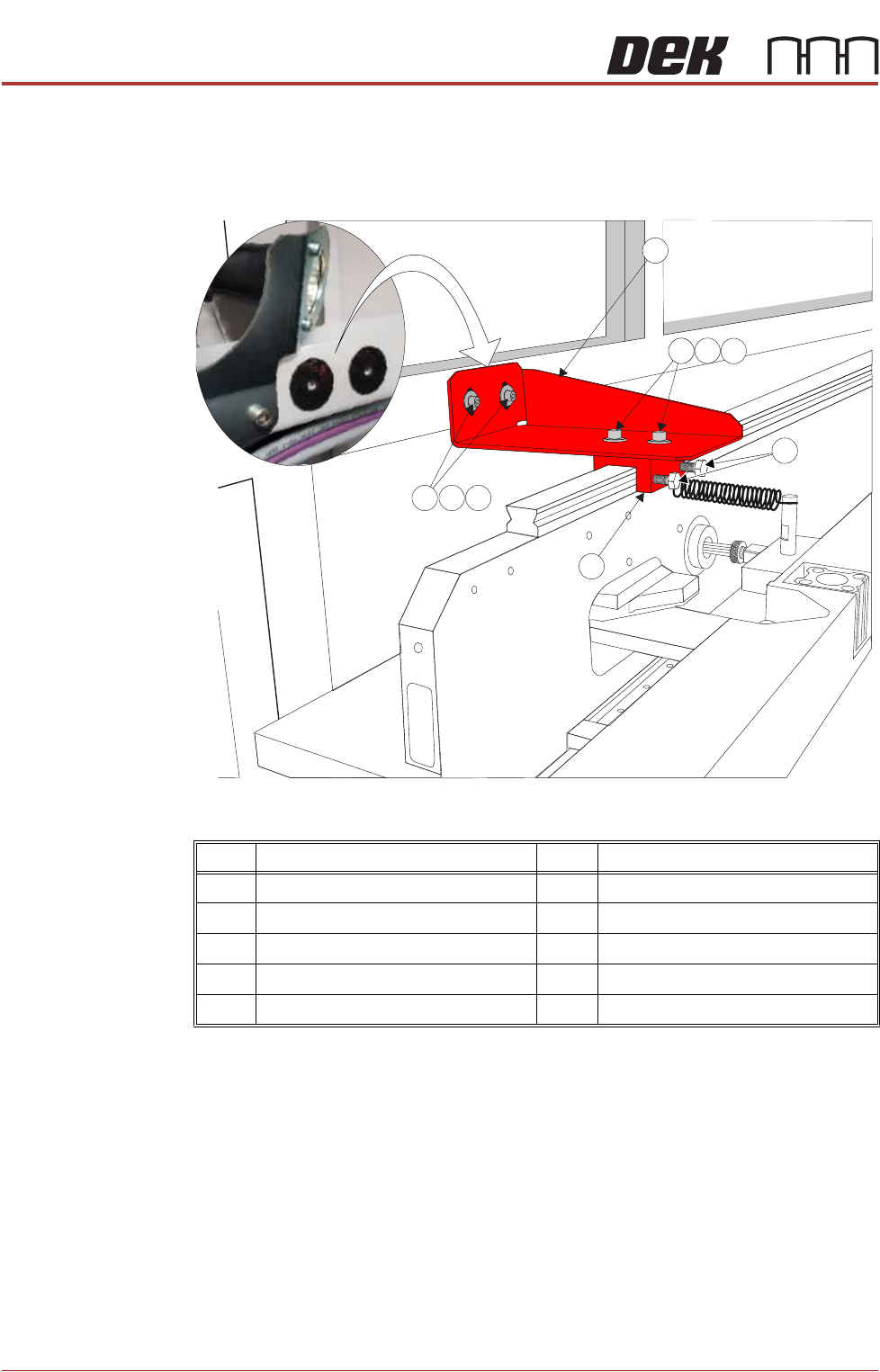
This bracket is to be fitted to printers with Anti Vibration (AV) mounts fitted to the
cover frame. It is located between the frame (adjacent to the print illumination
lights) and the carriage rail. There are neoprene washers stuck to the frame in
the position the transit bracket is to be fitted (See vignette in graphic below).
Figure 41-3 Cover Frame Transit Bracket
1. Ensure mating surfaces are clean and free of debris.
2. Place the cover frame transit bracket (1) and the block (6) (as an assembly)
over the carriage rail. The M5 screws (7) along with the crinkle washers (8)
and washers (9) should be sufficiently loose to allow adjustment.
3. Locate the M5 cap head screws (2) along with the crinkle washers (3) and
washers (4) through the bracket and into the frame and leave sufficiently
loose to allow movement.
4. Raise or lower the bracket (1) so it abuts the frame to achieve best fit and
the block is level on the carriage rail.
5. Tighten the M5 cap head screws (2).
6. Tighten the M5 cap head screws (7)
Item Description Item Description
1 Cover Frame Transit Bracket 6 Block
2 M5 Cap Head Screw 7 M5 Cap Head Screw
3 M5 Crinkle Washer 8 M5 Crinkle Washer
4 M5 Washer 9 M5 Washer
5 M6 Nylon Screw
3
4
2
9
8
5
1
6
7

TRANSPORTATION - MINOR RELOCATION
TRANSIT BRACKET INSTALLATION
Chapter Issue 4, May 19 Technical Reference Manual 41.7
7. Tighten the nylon screws (5) on to the carriage rail.
TRANSPORTATION - MINOR RELOCATION
TRANSPORTING THE MACHINE
41.8 Technical Reference Manual Chapter Issue 4, May 19
TRANSPORTING THE MACHINE
WARNING
MACHINE LIFTING. TO PREVENT SERIOUS INJURY TO PERSONNEL, DURING
LIFTING AND TRANSPORTATION OPERATIONS, ENSURE THE MACHINE IS
LIFTED AND TRANSPORTED IN ACCORDANCE WITH INSTRUCTIONS DETAILED
IN THIS SECTION.
NOTE
Damage to the machine will occur if the machine is lifted:
• Using lifting strops
OR . . .
• From the sides
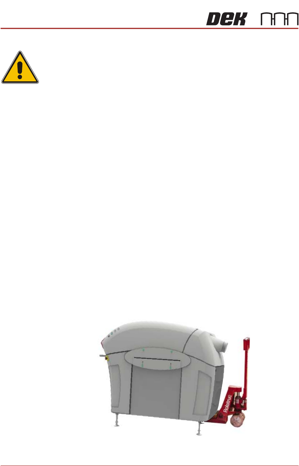
The machine may be lifted using a pallet truck or similar manually operated
machine that meets the following criteria:
• Minimum fork length of 1219mm (48 inches)
• Fork span >686mm (27 inches) and <914mm (36 inches)
• Fork Height (thickness) <50mm (2 inches)
• Lifting capability of 2000kg
1. Locate the forks under the machine base so the weight of the machine is
taken evenly on the front and rear cross members.
NOTE
Height of machine feet may have to be adjusted to allow the pallet truck to
raise the machine clear of the floor.
2. Raise the machine and carefully transport into position.
Figure 41-4 Machine on Pallet Truck