88192277-01-19 - Micron Technical Reference V9 Volume 4.pdf - 第174页
TRANSPORTATION - MAJOR RELOCATION TRANSIT BRACKET AND SCREW INS TALLATION 42.8 Technical Reference Manual Chapter Issue 5, Nov 19 Squeegee Mechanism T ransit Screws 1. By hand, gently raise the squeegee mechanism until t…
TRANSPORTATION - MAJOR RELOCATION
TRANSIT BRACKET AND SCREW INSTALLATION
Chapter Issue 5, Nov 19 Technical Reference Manual 42.7
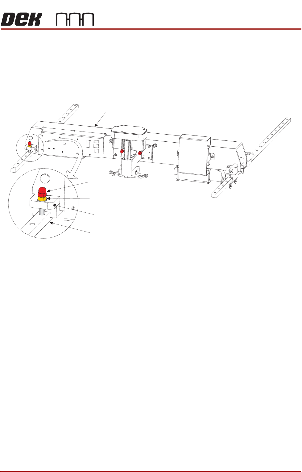
Print Carriage
Transit Screw
The left linear guide rail has sixteen holes for securing the rail to the printhead
of which only eight are used. The print carriage transit screw must be located
in a vacant hole and not one used by a rail securing screw.
1. Remove the plastic cap from the fifth hole from the front of the left linear
guide rail. Place the plastic cap in a re-sealable plastic bag and tape to the
print carriage.
2. Move the print carriage manually to align the hole of the print carriage
compliant bearing block with the hole in the left linear guide rail.
3. Ensure that an M8 nut and crinkle washer are fitted to the transit screw.
4. Fit the print carriage transit screw ensuring that the screw is fully tightened
down into the hole of the linear guide rail.
NOTE
The print carriage compliant bearing block is threaded allowing the transit
screw to locate in the hole of the linear guide rail without threading inside
the hole. This secures the print carriage from moving backwards or forwards
without exerting any downward force on the print carriage.
5. Tighten the locking nut down on to the print carriage compliant bearing block
to prevent the transit screw vibrating loose during transportation.
Print Carriage
Transit Screw
Print Carriage Compliant Bearing Block
Left Linear Guide Rail
Locking Nut and Crinkle Washer
TRANSPORTATION - MAJOR RELOCATION
TRANSIT BRACKET AND SCREW INSTALLATION
42.8 Technical Reference Manual Chapter Issue 5, Nov 19
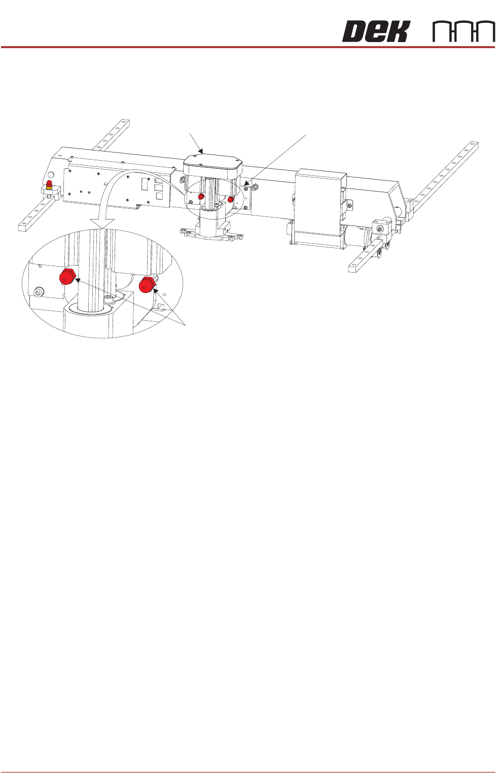
Squeegee
Mechanism Transit
Screws
1. By hand, gently raise the squeegee mechanism until the slots in the squee-
gee mechanism aligns with the holes in the squeegee mount.
2. Fit the two squeegee transit screws, one either side of the squeegee
mechanism, without over tightening the screw.
NOTE
The squeegee transit screws are designed to restrict the movement of the
squeegee mechanism and not to clamp the squeegee mechanism against
the squeegee mount.
3. Protect the front of the squeegee mechanism with a piece of card (300mm
x 180mm approximately) secured using cable ties.
Chase Brackets The chase transit brackets include the following:
• Front Transit Bracket
• Rear Transit Bracket
• Rear Chase Transit Bracket
Squeegee Transit Screws
Squeegee Mechanism Squeegee Mount
TRANSPORTATION - MAJOR RELOCATION
TRANSIT BRACKET AND SCREW INSTALLATION
Chapter Issue 5, Nov 19 Technical Reference Manual 42.9
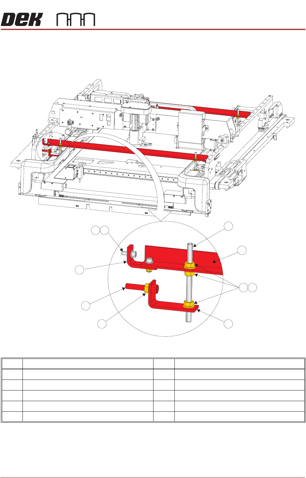
The figure below shows the transit brackets fully assembled for part identifica-
tion. Do not assemble off the machine, use the following procedure to assemble
the transit brackets on the machine.
Figure 42-3 Front and Rear Transit Brackets
NOTE
Item 5, the Left Chase Bracket is fitted upside down on dual lane machines.
Item Description Item Description
1 M8 Chase Stud 6 Transit Adjustment Screw Lock Nut
2 Front/Rear Transit Bracket 7 Transit Adjustment Screw
3 M8 Nut 8 Adaptor Bracket
4 M8 Washer 9 M5 Cap Head Screw
5 Left Chase Transit Bracket 10 M5 Washer
9
1
2
3
4
5
6
7
8
10