88192277-01-19 - Micron Technical Reference V9 Volume 4.pdf - 第278页
TRANSPORTATION - POWER UP PRE POWER UP CHE CKS 43.4 Technical Reference Manual Chapter Issue 3, Nov 19 External Services Figure 43-1 T ype 1, 2 and 3 Machines In order for the mach ine to function correctly the following…
TRANSPORTATION - POWER UP
PRE POWER UP CHECKS
Chapter Issue 3, Nov 19 Technical Reference Manual 43.3
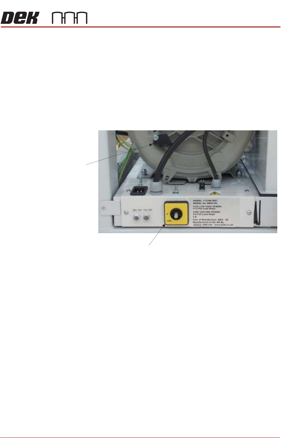
Vacuum Filtration
Unit
There are four types of onboard vacuum filtration unit, for use with the under
stencil cleaner, the VF30, the VF25, the VF10 and the VF35i. The VF30 and
VF25 are fixed voltage units factory set at either 115V or 230V, ensure that the
unit fitted matches the supply voltage.
The onboard VF35i vacuum filtration unit is dual voltage 115V/230V (50Hz/
60Hz) switchable from the front panel of the unit.
Ensure that the voltage selector switch, on the front panel of the onboard
vacuum filtration unit, is set to match the supply voltage. To check or switch the
voltage selector, carry out the following:
1. Using a 10mm spanner, remove the voltage selector control knob from the
fan housing.
2. Fit the voltage selector control knob to the voltage selector switch.
NOTE
The spindle has three keyways allowing the knob to be fitted in one position
only.
3. Ensure that the pointer of the knob is indicating the voltage that closely
matches the mains supply voltage.
NOTE
a. This unit is liable to damage if the voltage selector does not match the
supply voltage.
b. The ‘0’ position on the voltage selector is OFF disabling the vacuum
filtration unit.
4. Return the voltage selector control knob to the fan housing to prevent further
adjustment.
Voltage Selector Switch
Voltage
Selector
Control Knob
115v
TRANSPORTATION - POWER UP
PRE POWER UP CHECKS
43.4 Technical Reference Manual Chapter Issue 3, Nov 19
External Services
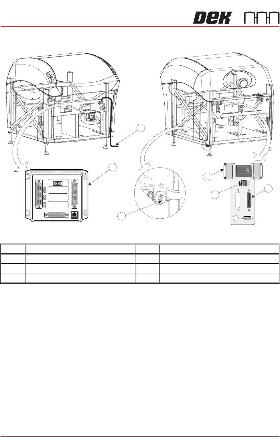
Figure 43-1 Type 1, 2 and 3 Machines
In order for the machine to function correctly the following services must be
available:
• Pneumatic Supply
• Electrical Supply
Other services that may be required are:
• Host Communications
• Upline/Downline Machine Interface (FMI/MIU)
• Temperature Control Module (TCM)
Item Description Item Description
1 Printer Mains Supply Cable 4 Foreign Machine Interface (FMI) Pod
2 Temperature Control Module (TCM) 5 Air Connection
3 Host Comms LAN RJ45 6 Multi Interface Unit (MIU)
M
1
S
K
1
M1SK1
U
P
L
I
N
E
UPL
I
N
E
M
1
S
K
2
M1
S
K
2
D
OW
N
L
I
N
E
DO
WNL
IN
E
M
1
PL
3
M
1
P
L3
DE
K
M
/C
DE
K
M
/
C
M
1S
K4
M
1
S
K
4
D
E
K
US
B
DEK
US
B
+1
2
V
+12
V
+2
4
V+2
4V
+
2
4
V S
W
+
2
4
V
S
W
SE
ND UP
L
IN
E
SE
N
D
U
P
L
I
NE
S
END
D
OW
NL
IN
E
S
END DOWNLI
N
E
CON
T
R
O
LINCON
TROL
IN
UP
L
INE
R
E
AD
YUP
L
I
NE
R
EAD
Y
DO
W
N
LI
N
E R
E
AD
Y
D
O
W
NLI
NE
R
EA
DY
CO
NTR
O
L
O
U
T
CO
NT
R
O
LO
U
T
P
O
W
E
R
P
O
W
E
R
I
/
P'SI
/
P
'
S
O
/
P
'S
O
/
P
'S
P
R
O
T
OC
O
L
S
E
LE
C
T
IO
N
PROTO
C
O
L
S
E
L
E
C
TI
ON
UPU
P
LIN
E
LINE
D
O
WNDOW
N
L
I
NEL
I
N
E
M
IU
1
9
1
11
4
MIU
1
91114
4
8
0
4
8
0
POWER ON
PART No. 160740
M/C AVAILABLE
BOARD AVAILABLE
BOARD PASS
D
O
W
N
LIN
E
BOARD AVAILABLE
BOARD PASS
M/C AVAILABLE
U
P
LIN
E
FMI POD
View on RearView on Front
1
2
3
4
5
6
M1SK1
UPLINE
M1SK2
DOWNLINE
M1PL3
DEK M/C
M1SK4
DEK USB
+12V
+24V
+24V SW
SEND UPLINE
SEND DOWNLINE
CONTROL IN
UPLINE READY
DOWNLINE READY
CONTROL OUT
POWER
I/P'S
O/P'S
PROTOCOL SELECTION
UP
LINE
DOWN
LINE
MIU 191114
4
80
4
80
TRANSPORTATION - POWER UP
PRE POWER UP CHECKS
Chapter Issue 3, Nov 19 Technical Reference Manual 43.5
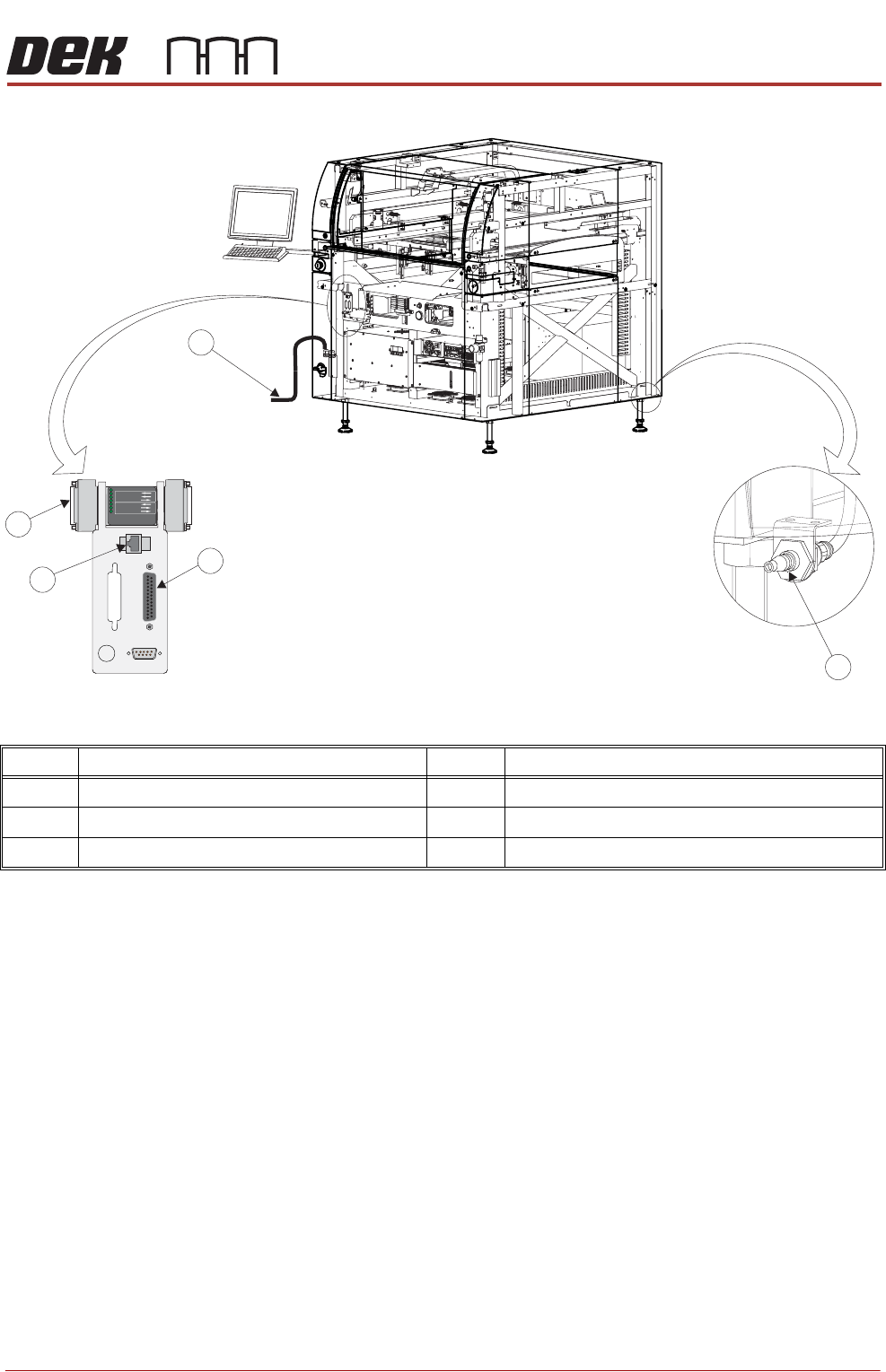
Figure 43-2 Type 4 Machine
In order for the machine to function correctly the following services must be
available:
• Pneumatic Supply
• Electrical Supply
Other services that may be required are:
• Host Communications
• Upline/Downline Machine Interface (FMI)
Item Description Item Description
1 Printer Mains Supply Cable 4 Host Comms Lan RJ45
2 Air Connection 5 Foreign Machine Interface (FMI) Pod
3 Temperature Control Module (TCM)
POWER ON
PART No. 160740
M/C AVAILABLE
BOARD AVAILABLE
BOARD PASS
D
O
W
N
L
IN
E
BOARD AVAILABLE
BOARD PASS
M/C AVAILABLE
U
P
L
IN
E
FMI POD
Front Right Quarter View
1
3
4
5
2