88192277-01-19 - Micron Technical Reference V9 Volume 4.pdf - 第271页
TRANSPORTATION - MAJOR RELOCATION MACHINE ASSEMBLY Chapter Issue 5, Nov 19 Technical Reference Manual 42.105 External Solvent T ank MANDA TOR Y TOXIC CHEMICALS MA Y BE PRESENT . SAFETY GLOVES MUST BE WORN. MANDA TOR Y TO…
TRANSPORTATION - MAJOR RELOCATION
MACHINE ASSEMBLY
42.104 Technical Reference Manual Chapter Issue 5, Nov 19
4. Remove the empty print medium cartridge and filler tube assembly.
NOTE
The filler tube assembly consists of the filler tube, the elbow fitting, and the
filler tube adaptor; these are removed as a single assembly.
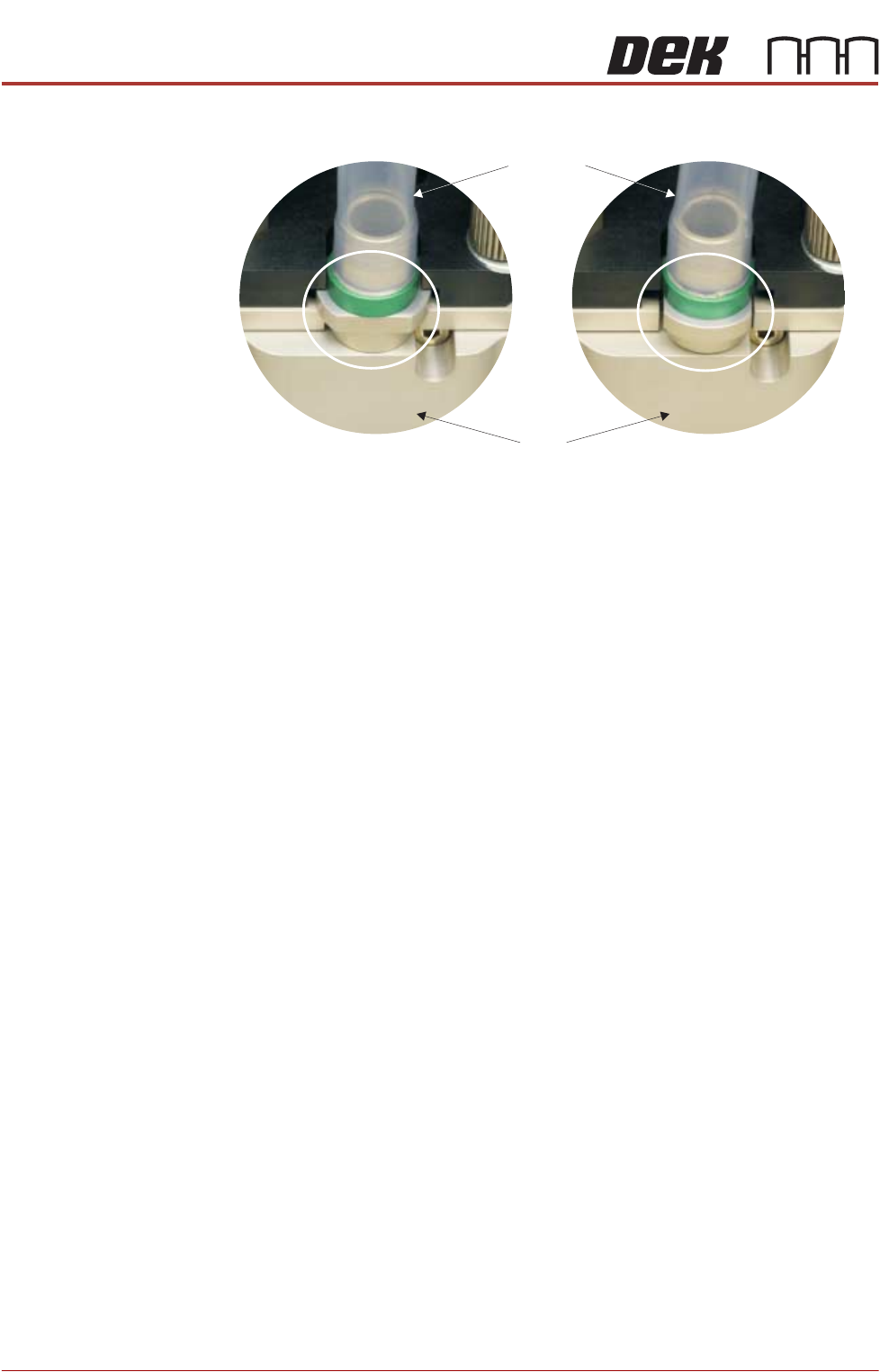
5. Unscrew the print medium cartridge from the filler tube assembly.
6. Dispose of the used print medium cartridge in accordance with any National,
Federal, or local waste disposal or recycling regulations.
7. Fit the new print medium cartridge to the filler tube assembly.
8. Fit the filler tube assembly to the transfer head.
9. Rotate the print medium cartridge clockwise 90° towards the ProFlow ATx
mount to lock the filler tube assembly into place.
NOTE
Ensure the print medium filler tube assembly rotates with the cartridge to its
locked position.
10. Close the print medium cartridge holder lever.
11. Close the machine cover.
View on Print Medium Filler Tube Assembly
Locked Position
Transfer
Head
Filler Tube
Assembly
Unlocked Position
TRANSPORTATION - MAJOR RELOCATION
MACHINE ASSEMBLY
Chapter Issue 5, Nov 19 Technical Reference Manual 42.105
External Solvent Tank
MANDATORY
TOXIC CHEMICALS MAY BE PRESENT. SAFETY GLOVES MUST BE WORN.
MANDATORY
TOXIC CHEMICALS MAY BE PRESENT. EYE PROTECTION MUST BE WORN.
NOTE
Changing solvent types may cause unexpected chemical reactions and degra-
dation within the solvent feed tube. ASM recommend that if the solvent is
changed to a different type, the solvent feed tube, from the solvent tank to the
cleaner pump, is replaced.
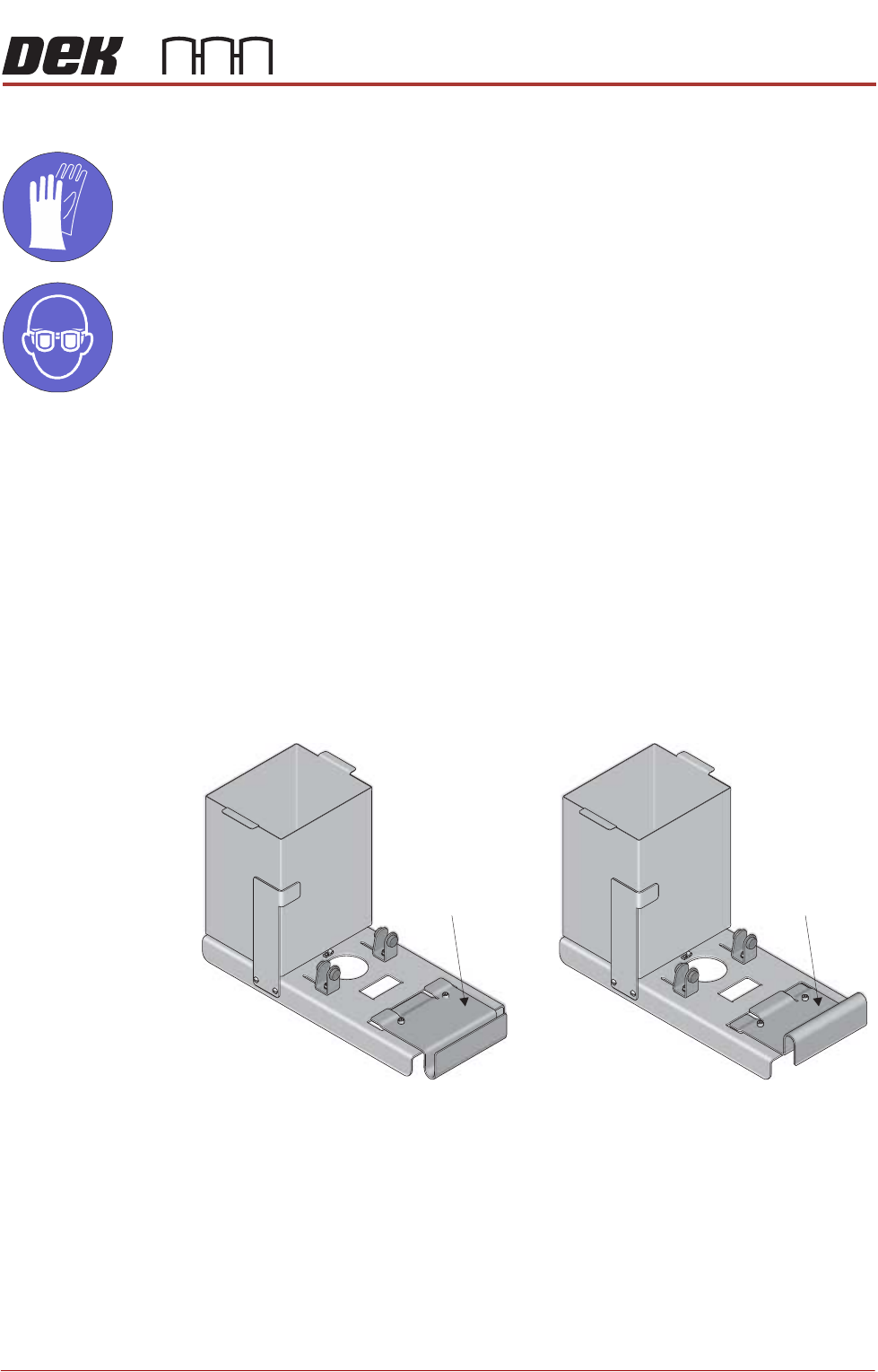
The external solvent tank may be fitted to the rear or the side of the machine.
The support plate on the external solvent tank is configured differently from side
or rear fitting due to baffle plates covering the cooling fans at the rear of the
machine.
To fit the external solvent tank carry out the following:
1. Configure the support plate of the external solvent tank for rear or side fitting
to the machine.
Rear Fitting Side Fitting
Support Plate Support Plate
TRANSPORTATION - MAJOR RELOCATION
MACHINE ASSEMBLY
42.106 Technical Reference Manual Chapter Issue 5, Nov 19
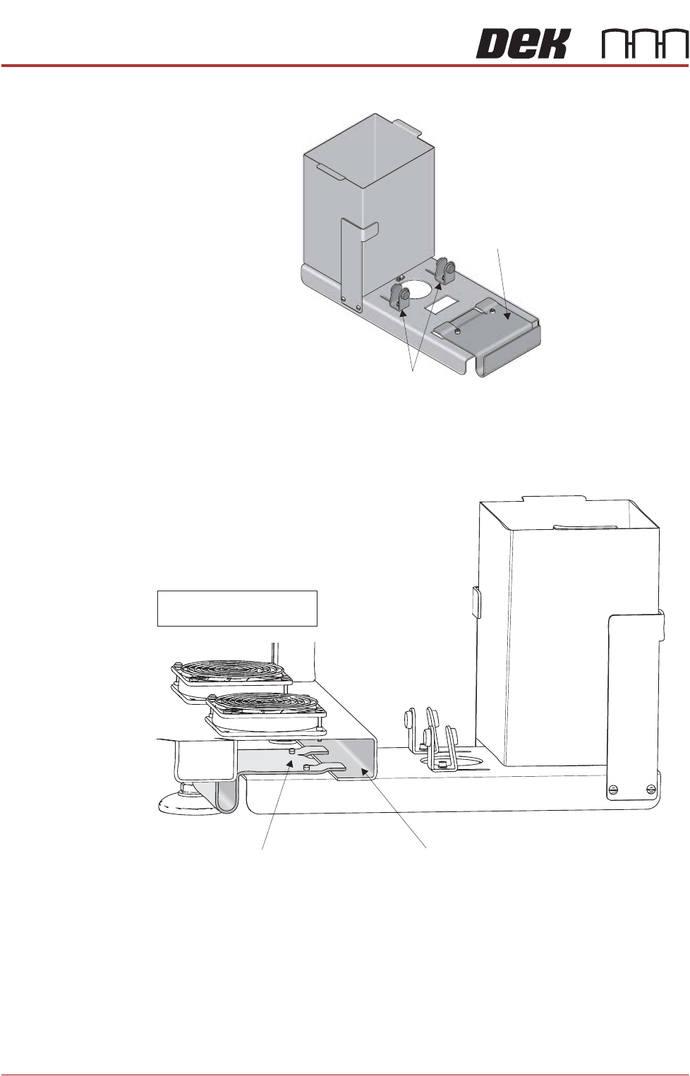
2. Move the angle brackets away from the support plate.
3. Remove the rear cover of the machine (front cover on type 4 machines).
4. Place the external solvent tank on the floor beneath its intended location.
5. Supporting its weight, lift the external solvent tank and locate the support
plate on the machine base frame, as shown in the graphic below:
6. Place a full solvent container into the external solvent tank.
7. Remove the cap from the solvent container.
8. Locate the combined solvent container cap and 4mm tubing, inside the
machine.
9. Pass the cap through the hole in the external solvent tank base plate, from
underneath.
Support Plate
Angle Brackets
Support Plate Machine Base Frame (Cross Section)
NOTE
Baffles removed for clarity