88192277-01-19 - Micron Technical Reference V9 Volume 4.pdf - 第92页
DIAGNOSTI CS SYSTEM 39.6 Technical Reference Manual Chapter Issue 4, Aug 14 Node 4 Group 2 Node 6 Group 0 Node 7 Group 0 Node 8 Group 0 Node 4 Group 2 Point Description --------------------- --------- ------- Bit No Sens…
DIAGNOSTICS
SYSTEM
Chapter Issue 4, Aug 14 Technical Reference Manual 39.5
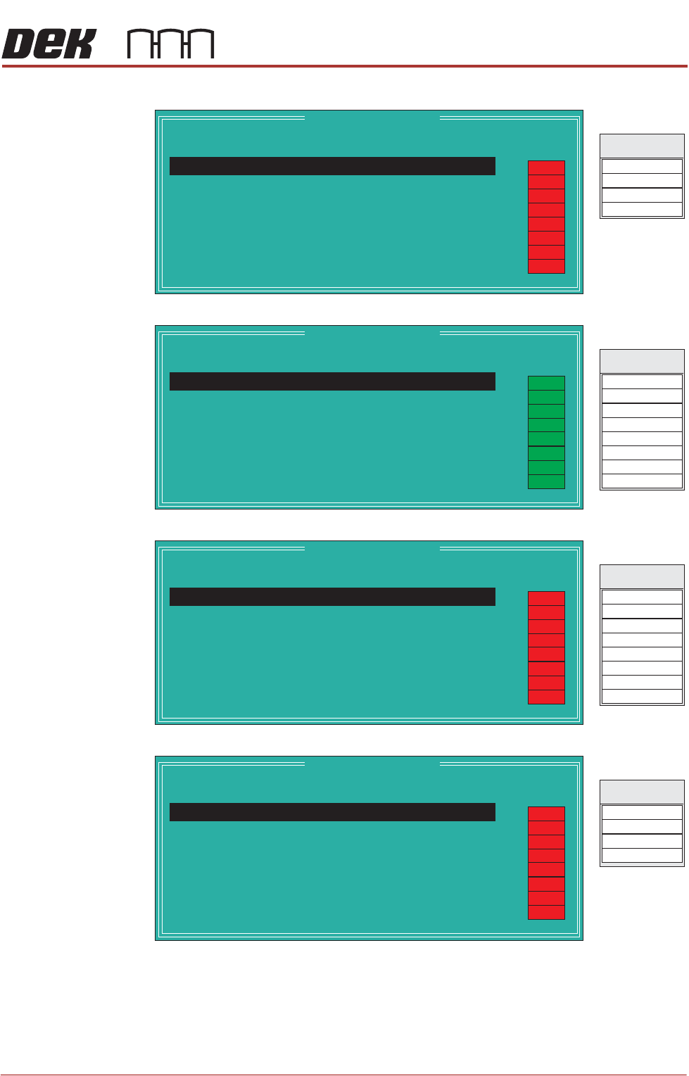
Node 3 Group 1
Node 3 Group 2
Node 4 Group 0
Node 4 Group 1
Node 3 Group 1
Point Description
---------------------
---------
-------
Bit No
Sense
-----------
------
Direction
State
Cartridge Empty
Not Used
Not Used
1
2
3
Nega
Nega
Nega
tive
tive
tive
Input
Input
Input
OFF
DIG IN 8
DIG IN 9
Signal
DIG IN 10
DIG IN 11
Cartridge Home
0
Positive
Input
OFF
OFF
OFF
OFF
OFF
OFF
OFF
Node 3 Group 2
Point Description
---------------------
---------
-------
Bit No
Sense
-----------
------
Direction
State
Not Used
Not Used
ProFlow Reg Control
Dispense Paste
Tilt Cartridge Away
Drip Tray Actuator
Screen Stop Actuator
1
2
3
4
5
6
7
Negative
Negative
Negative
Negative
Negative
Negative
Negative
Output
Output
Output
Output
Output
Output
Output
DIG OUT 0
DIG OUT 4
DIG OUT 1
Signal
DIG OUT 5
DIG OUT 6
DIG OUT 2
DIG OUT 3
DIG OUT 7
Roll Height Monitor Las
0
Negative
Output
ON
ON
ON
ON
ON
ON
ON
ON
Node 4 Group 0
Point Description
---------------------
---------
-------
Bit No
Sense
-----------
------
Direction
State
Paper Low
Cleaning Unit Home
USC Vacuum Sense
Levelness Screen Sense
Levelness Cylinder Ext
Not Used
Not Used
1
2
3
4
5
6
7
Nega
Nega
Nega
Nega
Nega
Nega
tive
Positive
tive
tive
tive
tive
tive
Input
Input
Input
Input
Input
Input
Input
DIG IN 0
DIG IN 4
DIG IN 1
Signal
DIG IN 5
DIG IN 6
DIG IN 2
DIG IN 3
DIG IN 7
Solvent Low
0
Negative
Input
OFF
OFF
OFF
OFF
OFF
OFF
OFF
OFF
Node 4 Group 1
Point Description
---------------------
---------
-------
Bit No
Sense
-----------
------
Direction
State
Not Used
Cleaner Dropped
Not Used
1
2
3
Nega
Nega
Nega
tive
tive
tive
Input
Input
Input
DIG IN 8
DIG IN 9
Signal
DIG IN 10
DIG IN 11
Not Used
0
Negative
Input
OFF
OFF
OFF
OFF
OFF
OFF
OFF
OFF
DIAGNOSTICS
SYSTEM
39.6 Technical Reference Manual Chapter Issue 4, Aug 14
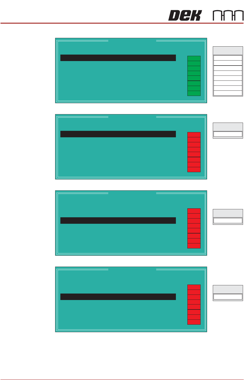
Node 4 Group 2
Node 6 Group 0
Node 7 Group 0
Node 8 Group 0
Node 4 Group 2
Point Description
---------------------
---------
-------
Bit No
Sense
-----------
------
Direction
State
Solvent Pinch Valve
Cleaner Paper Feed
Cleaner Vacuum
Oscillating Motor
Not Used
Not Used
Not Used
1
2
3
4
5
6
7
Negative
Negative
Negative
Negative
Negative
Negative
Negative
Output
Output
Output
Output
Output
Output
Output
DIG OUT 0
DIG OUT 4
DIG OUT 1
Signal
DIG OUT 5
DIG OUT 6
DIG OUT 2
DIG OUT 3
DIG OUT 7
Cleaner Home Clamp
0
Negative
Output
ON
ON
ON
ON
ON
ON
ON
ON
Node 6 Group 0
Point Description
---------------------
---------
-------
Bit No
Sense
-----------
------
Direction
State
DIG IN 0
Signal
Table at Home
0
Positive
Input
OFF
OFF
OFF
OFF
OFF
OFF
OFF
OFF
Node 7 Group 0
Point Description
---------------------
---------
-------
Bit No
Sense
-----------
------
Direction
State
DIG IN 2
Signal
Print Carriage Home
2
Positive
Input
OFF
OFF
OFF
OFF
OFF
OFF
OFF
OFF
Node 8 Group 0
Point Description
---------------------
---------
-------
Bit No
Sense
-----------
------
Direction
State
DIG IN 2
Signal
Camera X Home
2
Positive
Input
OFF
OFF
OFF
OFF
OFF
OFF
OFF
OFF
DIAGNOSTICS
SYSTEM
Chapter Issue 4, Aug 14 Technical Reference Manual 39.7
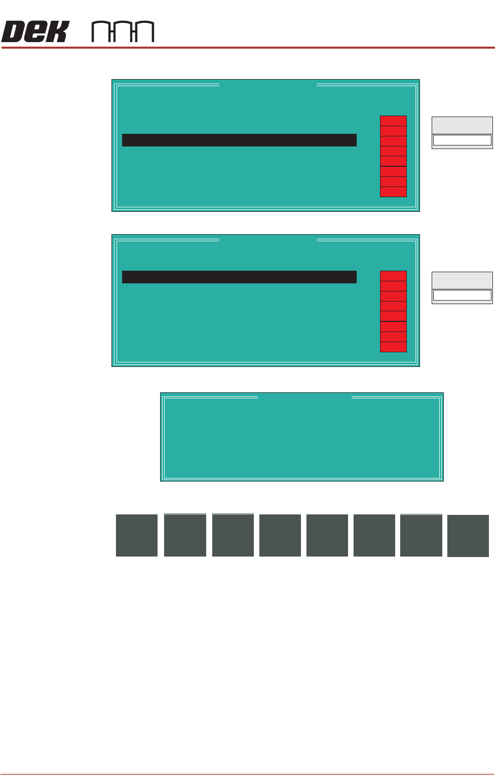
Node 9 Group 0
Node 10 Group 0
Display All
Analogue Inputs
Selecting this diagnostic function opens the following window:
The following icons are displayed:
Exit returns operation to the system diagnostics page.
Node 9 Group 0
Point Description
---------------------
---------
-------
Bit No
Sense
-----------
------
Direction
State
DIG IN 2
Signal
Camera Y Home
2
Positive
Input
OFF
OFF
OFF
OFF
OFF
OFF
OFF
OFF
Node 10 Group 0
Point Description
---------------------
---------
-------
Bit No
Sense
-----------
------
Direction
State
DIG IN 0
Signal
Paste Carriage Home
0
Positive
Input
OFF
OFF
OFF
OFF
OFF
OFF
OFF
OFF
Analogue I/O Values
Description
--------------
----------------
Integer Value
--------------------
Converted Value
Pressure Sensor
Temperature
Relative Humidity
Solvent Tank Level
ProFlow Medium Level
2327
3644
2985
345
857
8.51 kg
24.573 C
42.386 %
64 %
12 %
o
Exit