88192277-01-19 - Micron Technical Reference V9 Volume 4.pdf - 第51页
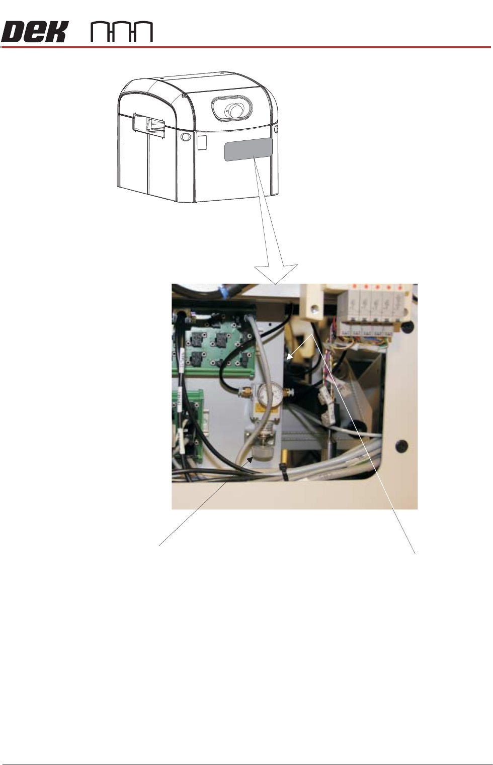
STINGER ELEMENTS Chapter Issue 4, Nov 19 Technical Reference Manual 38.9 Figure 38-2 Air Pressure Re gulator and Control Interface Location (Behind Rear Panel) Contro l I nterface (at rear of pane l ) Regu l ator
38.8 Technical Reference Manual Chapter Issue 4, Nov 19
STINGER
ELEMENTS
sure regulator sets pneumatic pressure.
The control interface is responsible for interfacing with the printing machine and
locally controlling Stinger’s functions: axis control, motor moves and air pulsing.
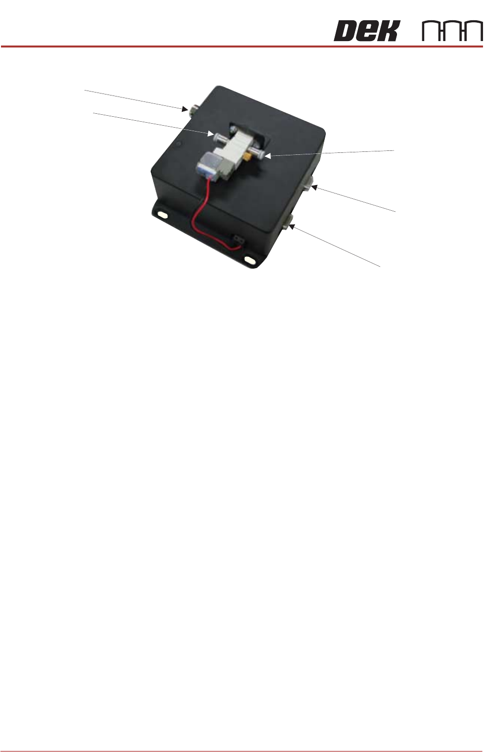
Electrical Power In
Stinger Power & Signal
Serial RS232 to PC
Air Input Connector
Air Output Connector
Control Interface
STINGER
ELEMENTS
Chapter Issue 4, Nov 19 Technical Reference Manual 38.9
Figure 38-2 Air Pressure Regulator and Control Interface Location
(Behind Rear Panel)
Control Interface
(at rear of panel)
Regulator
38.10 Technical Reference Manual Chapter Issue 4, Nov 19
STINGER
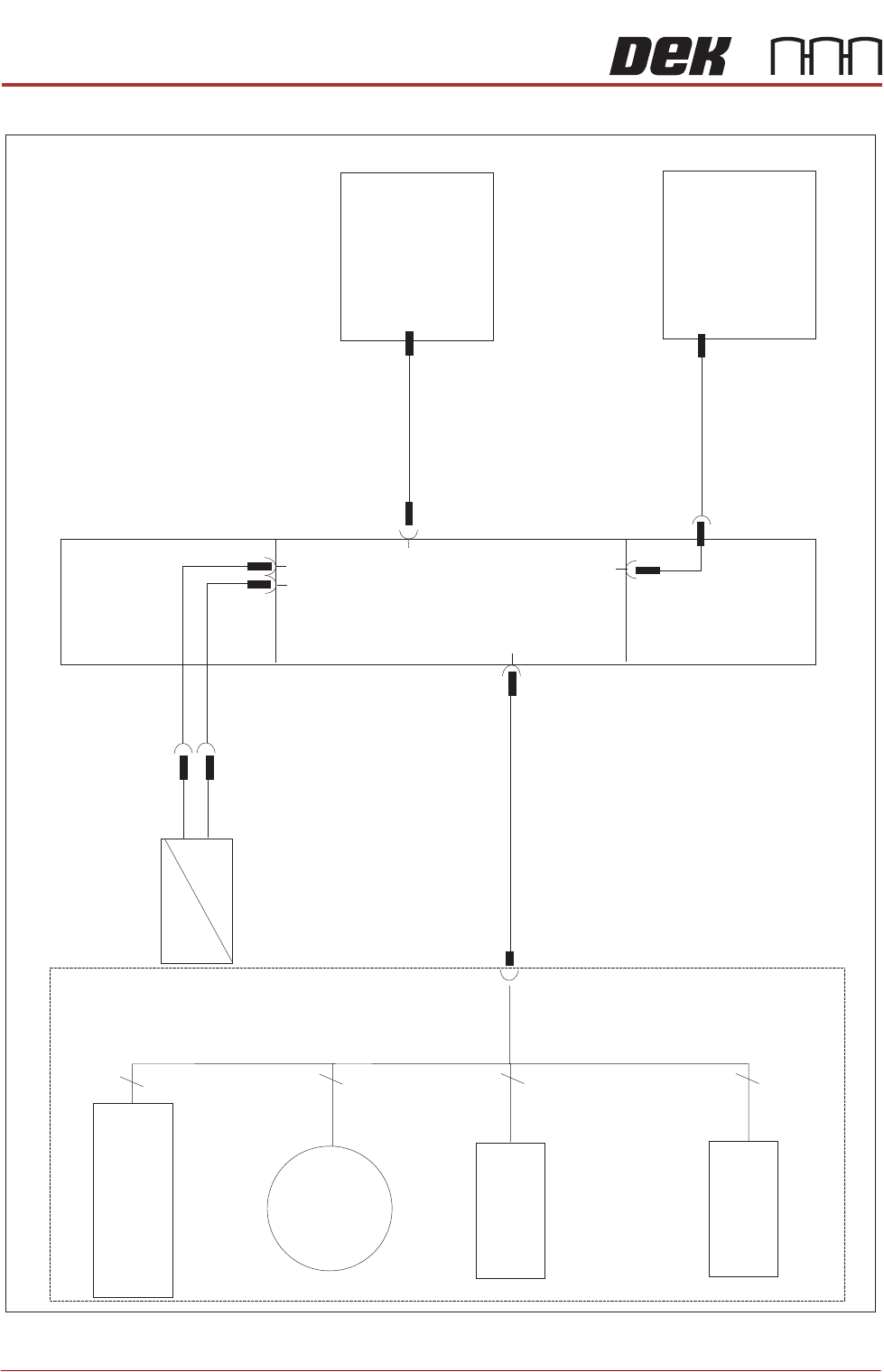
ELECTRICAL SHEMATIC
ELECTRICAL SHEMATIC
M37 PSU
IBUS PC
4
3
4
4
M37PL10
8PL34
M48SK02
M48PL07
M48SK07
M48PL01
M48PL05
M48PL06
M48SK06
M48PL08
M48PL09
M48SOL01
Air Feed
Pneumatic Cylinder
Stinger
Enclosure
Stinger
Board
Laser Sensor
M48SE01
Consumable
Level Sensor
M48SE02
Dispense
Motor
M48M01
Z Axis
Motor (Linear Actuator)
M48M02