88192277-01-19 - Micron Technical Reference V9 Volume 4.pdf - 第298页
TRANSPORTATION - POWER UP FOREIGN MACHINE INTERFAC E 43.24 Technical Reference Manual Chapter Issue 3, Nov 19 FOREIGN MACHINE INTERF ACE Introduction The Foreign Machine Interface (FMI) is an electrical means of co mmuni…
TRANSPORTATION - POWER UP
HIGH THROUGHPUT CONVEYOR (HTC)
Chapter Issue 3, Nov 19 Technical Reference Manual 43.23
3. Run the feeler gauge along the whole length of the conveyor rail, the fit of
the feeler gauge should be tight, between the plate and the inner face of the
rail.
4. Remove the feeler gauge and manually move the plate in and out of the
machine along the conveyor transport belts, ensuring the plate moves freely
without binding or jamming.
If adjustment is required, carry out the following:
5. Loosen the two rear rail securing bolts, adjust the rail to achieve parallelism
and re-tightening the rail securing bolts.
6. Repeat Steps 2 to 5 to recheck for parallelism.
7. Repeat Steps 1 to 6 for the left hand auxiliary conveyor.
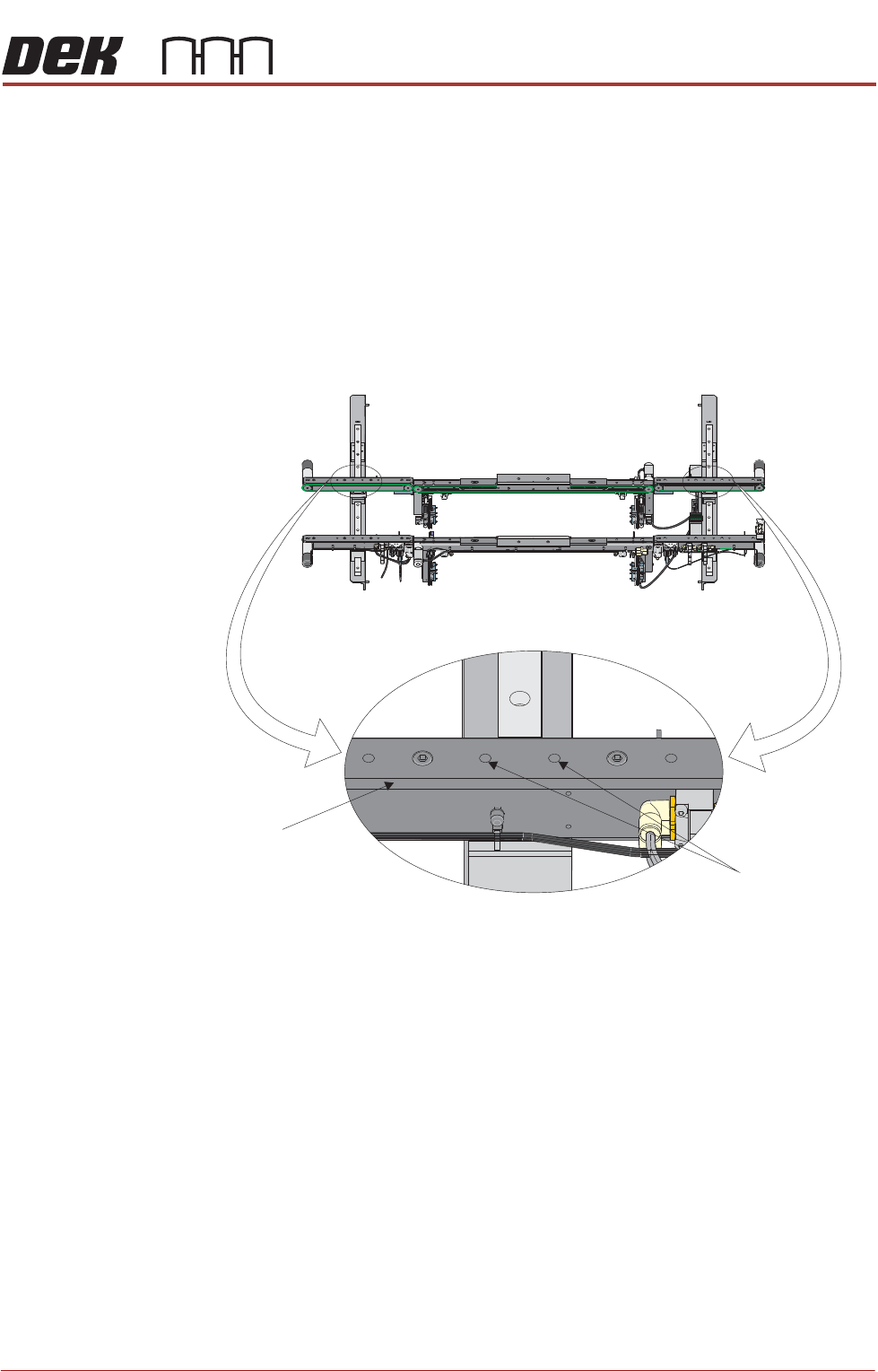
Front View of HTC Rails
Auxiliary Conveyor
Rear Rail
Rear Rail
Securing Bolts
TRANSPORTATION - POWER UP
FOREIGN MACHINE INTERFACE
43.24 Technical Reference Manual Chapter Issue 3, Nov 19
FOREIGN MACHINE INTERFACE
Introduction The Foreign Machine Interface (FMI) is an electrical means of communication
between the DEK machine and an adjacent machine/conveyor, using electrical
signals. The signals are transferred using opto-couplers and/or solid state
relays which keep the machines electrically isolated.
The DEK machine can interface with many different types of adjacent machine.
The adjacent machine utilizes a set of timing and control signals (protocols) for
communication with other machines. There are two different types of interface
available:
• An FMI Pod for SMEMA, Fuji or Panasonic protocols
• A Multi-Interface Unit (MIU) for all other protocols
The FMI Pod and the MIU are supplied with the following cables:
• An FMI loom which connects the FMI port on the machine controller, to the
MIU or FMI Pod
• Two interface cables, one cable for each adjacent machine
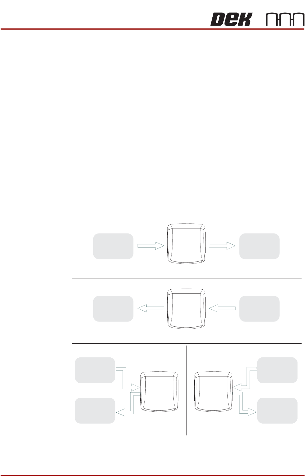
The adjacent machine/conveyor can be in the following configurations:
Figure 43-5 Machine Arrangements for Board Transfers
Left to Right Board Transfers
Right to Left Board Transfers
Upline
Downline
UplineDownline
Left to Left Board Transfers Right to Right Board Transfers
Upline
Downline
Upline
Downline
DEK
Machine
DEK
Machine
DEK
Machine
DEK
Machine
Adjacent
Machine/
Conveyor
Adjacent
Machine/
Conveyor
Adjacent
Machine/
Conveyor
Adjacent
Machine/
Conveyor
Adjacent
Machine/
Conveyor
Adjacent
Machine/
Conveyor
Adjacent
Machine/
Conveyor
Adjacent
Machine/
Conveyor
TRANSPORTATION - POWER UP
FOREIGN MACHINE INTERFACE
Chapter Issue 3, Nov 19 Technical Reference Manual 43.25
FMI Pod The FMI Pod is only used where both the upline and downline is using SMEMA,
Fuji or Panasonic interfaces. For all other interfaces refer to the MIU interface
later in this chapter.
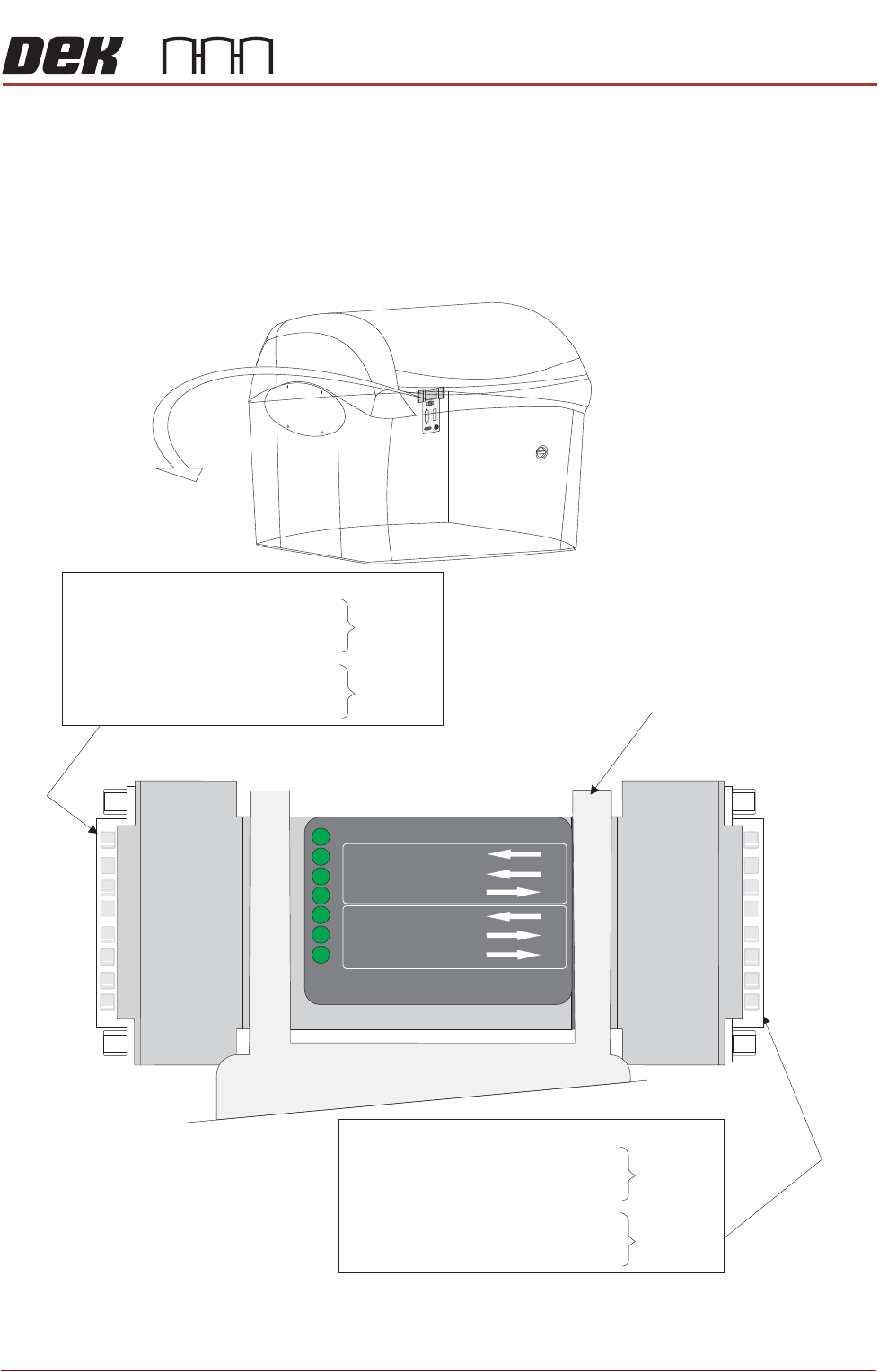
The DEK FMI Pod, located on the external services panel at the rear of the
machine, is a communications interface that allows machine to communicate
with upline and downline board handlers.
03 Board Available (Input)
10 Board Pass (Input)
01 Dek M/C Available (Output)
16 Downline M/C Available (Input)
19 Board Available (Output)
24 Board Pass (Output)
Upline
Downline
M28SK02
External Service Panel
POWER ON
PART No. 189634
M/C AVAILABLE
BOARD AVAILABLE
BOARD PASS
DOWNLINE
BOARD AVAILABLE
BOARD PASS
M/C AVAILABLE
UPLINE
18 Board Available (Input)
05 Board Pass (Input)
15 Dek M/C Available (Output)
09 Downline M/C Available (Input)
06 Board Available (Output)
13 Board Pass (Output)
Upline
Downline
M28PL01
FMI POD