88192277-01-19 - Micron Technical Reference V9 Volume 4.pdf - 第148页
TRANSPORTATION - MINOR RELOCATION TRANSIT BRACKET INSTALLATION 41.6 Technical Reference Manual Chapter Issue 4, May 19 Cover Frame T ransit Bracket This bracket is to be fitted to print ers with Anti Vibration (A V) moun…
TRANSPORTATION - MINOR RELOCATION
TRANSIT BRACKET INSTALLATION
Chapter Issue 4, May 19 Technical Reference Manual 41.5
12. Loosely attach the adaptor bracket (8) at each end of the front and rear
transit bracket (2) to the left and right printheads using an M5 cap head
screw (9) and M5 washer (10).
13. Screw an M8 nut (3) and M8 washer (4) onto each of the four M8 chase
studs (1) and adjust so that the front and rear transit brackets are nipped
between the nuts and washers, ensuring that the chase is not lifted at this
time.
14. Fully tighten the M5 cap head screws (9) left loose in Step 12.
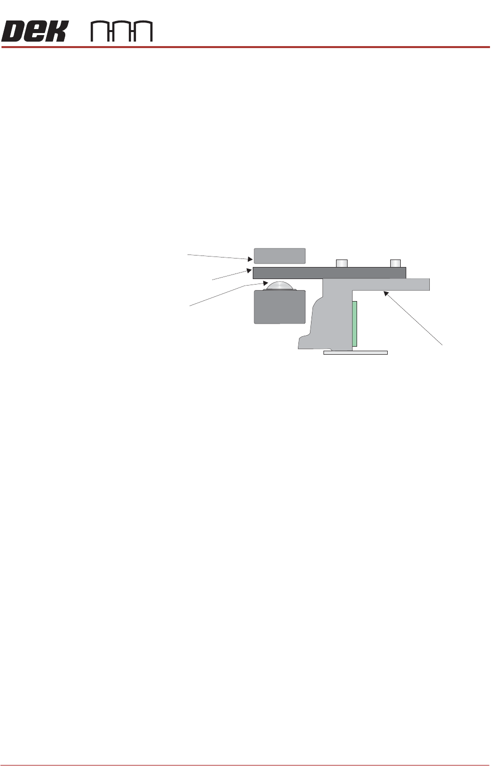
15. Slacken the M8 nuts (3) directly below the front and rear transit brackets (2).
16. Adjust the M8 nuts (3) above the front and rear transit brackets (2) to lift the
chase off the roller bearings (in all four positions), ensuring that the roller
counter plates are not touching the chase clamps.
17. Tighten the M8 nuts (3) directly below the front and rear transit brackets (2).
18. Refit/close any disturbed covers.
Chase
Chase Clamp
Roller Bearing
Roller Counter Plate
TRANSPORTATION - MINOR RELOCATION
TRANSIT BRACKET INSTALLATION
41.6 Technical Reference Manual Chapter Issue 4, May 19
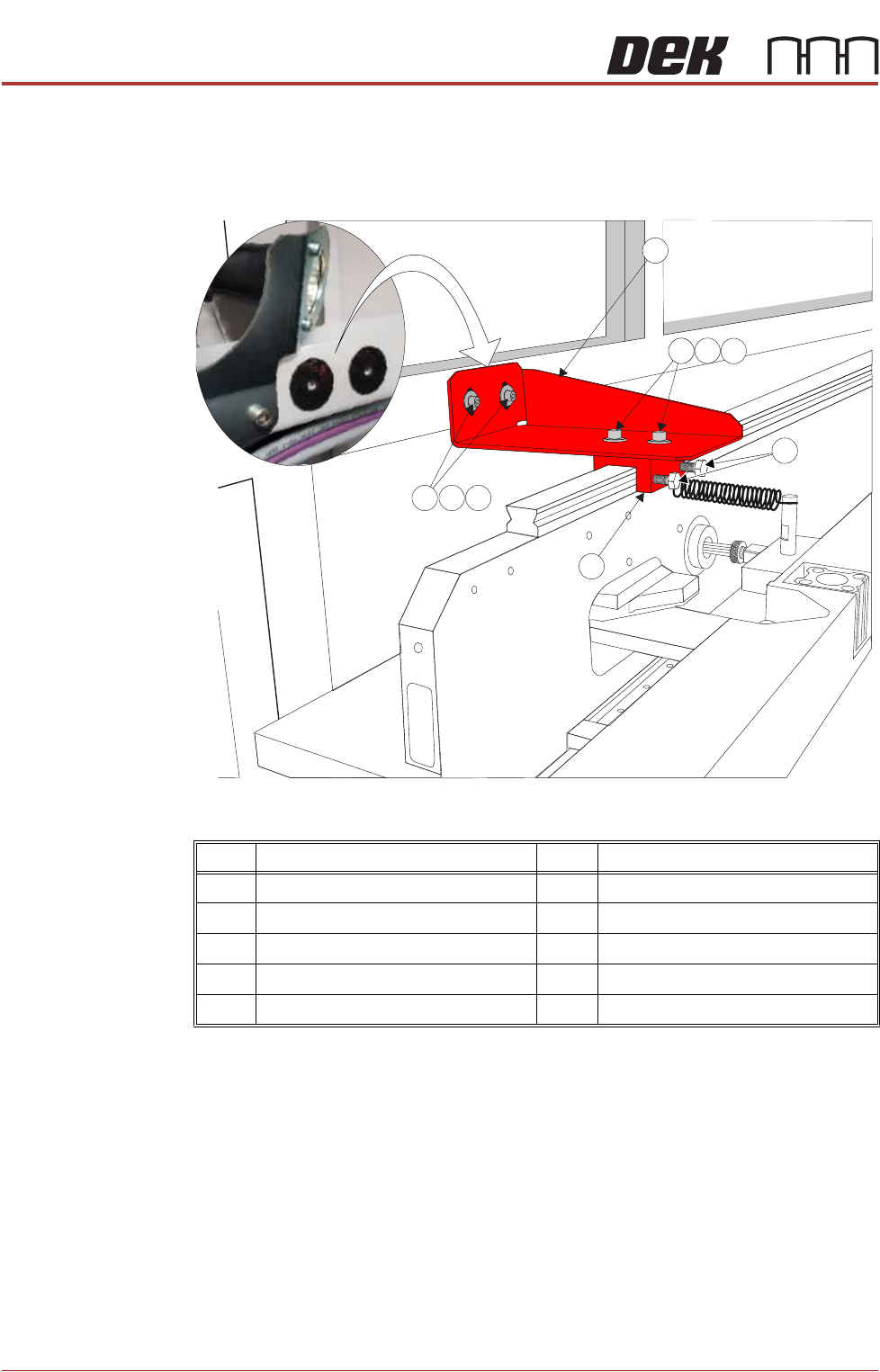
Cover Frame
Transit Bracket
This bracket is to be fitted to printers with Anti Vibration (AV) mounts fitted to the
cover frame. It is located between the frame (adjacent to the print illumination
lights) and the carriage rail. There are neoprene washers stuck to the frame in
the position the transit bracket is to be fitted (See vignette in graphic below).
Figure 41-3 Cover Frame Transit Bracket
1. Ensure mating surfaces are clean and free of debris.
2. Place the cover frame transit bracket (1) and the block (6) (as an assembly)
over the carriage rail. The M5 screws (7) along with the crinkle washers (8)
and washers (9) should be sufficiently loose to allow adjustment.
3. Locate the M5 cap head screws (2) along with the crinkle washers (3) and
washers (4) through the bracket and into the frame and leave sufficiently
loose to allow movement.
4. Raise or lower the bracket (1) so it abuts the frame to achieve best fit and
the block is level on the carriage rail.
5. Tighten the M5 cap head screws (2).
6. Tighten the M5 cap head screws (7)
Item Description Item Description
1 Cover Frame Transit Bracket 6 Block
2 M5 Cap Head Screw 7 M5 Cap Head Screw
3 M5 Crinkle Washer 8 M5 Crinkle Washer
4 M5 Washer 9 M5 Washer
5 M6 Nylon Screw
3
4
2
9
8
5
1
6
7

TRANSPORTATION - MINOR RELOCATION
TRANSIT BRACKET INSTALLATION
Chapter Issue 4, May 19 Technical Reference Manual 41.7
7. Tighten the nylon screws (5) on to the carriage rail.