88192277-01-19 - Micron Technical Reference V9 Volume 4.pdf - 第132页
SENSORS CAPACITIVE PROXIMITY SENSOR 40.10 Technical Reference Manual Chapter Issue 6, May 19 T esting/ Adjustment Figure 40-13 V oltage Diagram Setting Up Procedure The procedure for setting up the capa citive proximity …
SENSORS
CAPACITIVE PROXIMITY SENSOR
Chapter Issue 6, May 19 Technical Reference Manual 40.9
CAPACITIVE PROXIMITY SENSOR
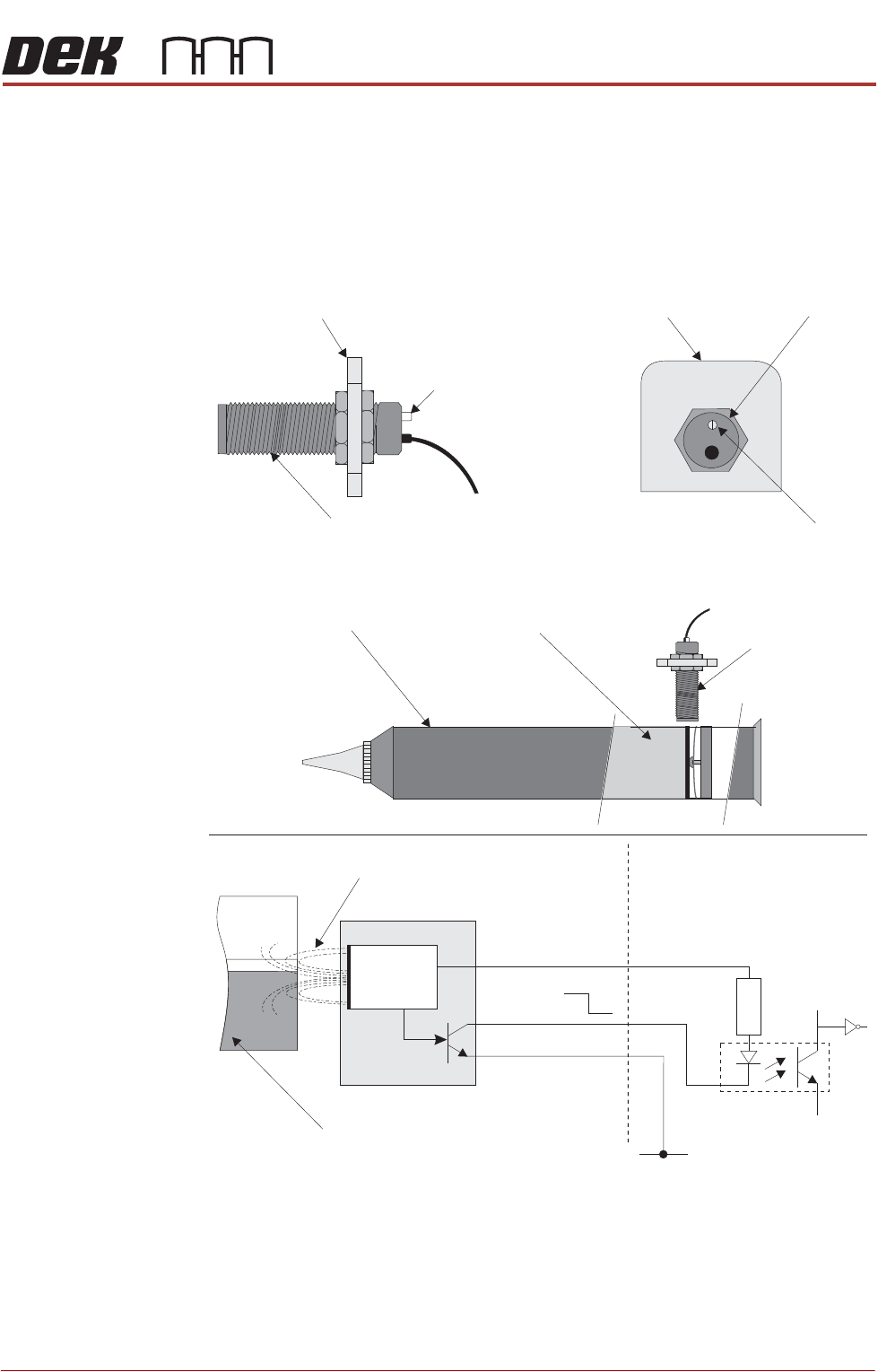
Description A capacitive proximity sensor consists of an RC oscillator which emits a
frequency field. When the target, in this case the solder paste, moves away
from the sensing range (ie paste low), the capacitance increase effectively
changes the internal current which is detected by an adjustable trigger. The
control circuit switches the output transistor on.
Figure 40-12 Capacitive Proximity Sensor
Capacitive Proximity Switch
Sensor Bracket
LED
Paste Level Sensor
LED Adjuster
and Indicator
Sensor Bracket
Sensor
PastePaste Cartridge
Paste Level
Sensor
+V
Opto-isolator
1K8
0V
0V
12V
RC Frequency Field
Solder Paste
12V
0V
Pin 1
Control
Circuit
Pin 2
Pin 3
Digital Input

SENSORS
CAPACITIVE PROXIMITY SENSOR
40.10 Technical Reference Manual Chapter Issue 6, May 19
Testing/
Adjustment
Figure 40-13 Voltage Diagram
Setting Up
Procedure
The procedure for setting up the capacitive proximity sensor is fully detailed in
the Paste Dispenser System chapter of this manual, (Adjustments and Settings
section).
Node Absent Present Absent
12V
0V
Off OffOn
Operation Indicator
Signal
SENSORS
REED SWITCH SENSOR
Chapter Issue 6, May 19 Technical Reference Manual 40.11
REED SWITCH SENSOR
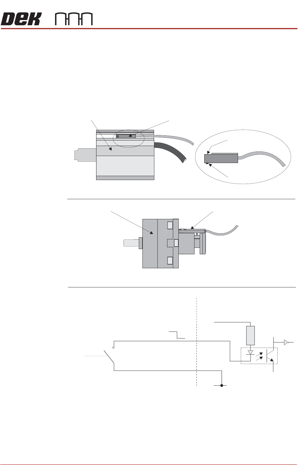
Description A reed switch is activated by a magnet fitted to either the piston or drive shaft
of the actuator. One side of the switch is connected to the input, the other side
of the reed switch is connected to 0V. The input is connected to +12V via a pull
up resistor, so under normal conditions the input is pulled high. When the reed
switch is activated by a magnet, the reed switch closes and pulls the input down
to 0V (low).
Figure 40-14 Reed Switch Schematic
Digital Input
+V
Opto-isolator
(Red)
(Black)
1K8
0V
12V
0V
N0
(normally open)
Locking Screw
Sensor
Pneumatic Cylinder Reed Switch
Pneumatic Cylinder with Reed Switch
Rotary Actuator
Rotary Actuator with Reed Switch
Board Stop In Reed Switch