88192277-01-19 - Micron Technical Reference V9 Volume 4.pdf - 第137页
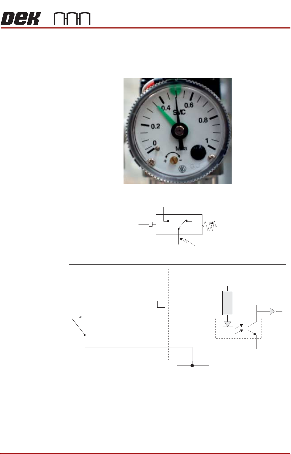
SENSORS PRESSURE SENSOR Chapter Issue 6, May 19 Technical Reference Manual 40.15 PRESSURE SENSOR Description The pressure sensor switch is wired as a normally open (NO) switch which is closed by the air pressure exceedin…

SENSORS
SAFETY SWITCH
40.14 Technical Reference Manual Chapter Issue 6, May 19
Testing/
Adjustment
To adjust the safety switch, physically move the body of the switch to ensure
that 6mm of cover movement activates the switch.
Figure 40-17 Voltage Diagram
Cover Closed Open Closed
12V
0V
Closed
Circuit
Closed
Circuit
Open
Circuit
Continuity
Signal
SENSORS
PRESSURE SENSOR
Chapter Issue 6, May 19 Technical Reference Manual 40.15
PRESSURE SENSOR
Description The pressure sensor switch is wired as a normally open (NO) switch which is
closed by the air pressure exceeding the set point.
Figure 40-18 Pressure Sensor Schematic
Digital Input
+V
Opto-isolator
1K8
0V
12V
0V
Pressure Sensor Symbol
Pressure Sensor and Gauge
P
Common
NC
NO
SENSORS
PRESSURE SENSOR
40.16 Technical Reference Manual Chapter Issue 6, May 19
Testing/
Adjustment
For adjustment refer to the Pneumatic Module Chapter.
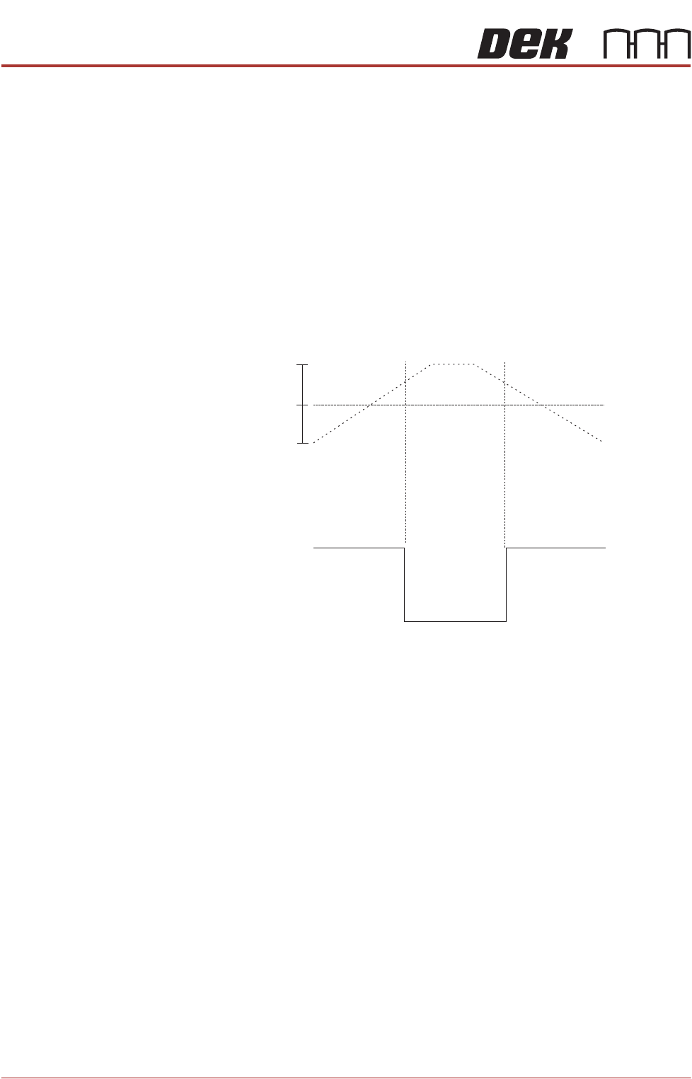
The sensor may be tested either in circuit or disconnected:
In circuit -
• Monitor the voltage at signal DIG IN 0 whilst increasing the pressure from
zero using the main regulator. As the air pressure exceeds the set point
value the voltage is pulled down to 0V.
Disconnected -
• Measure continuity across the switch whilst increasing the pressure from
zero using the main regulator. As the air pressure exceeds the set point
value the contacts close.
Figure 40-19 Pressure Diagram
Indicated
Pressure
12V
0V
Open
Circuit
Closed
Circuit
Open
Circuit
Set Point
Contact
Continuity
Digital I/P
Signal
5
3
bar
0