88192277-01-19 - Micron Technical Reference V9 Volume 4.pdf - 第90页
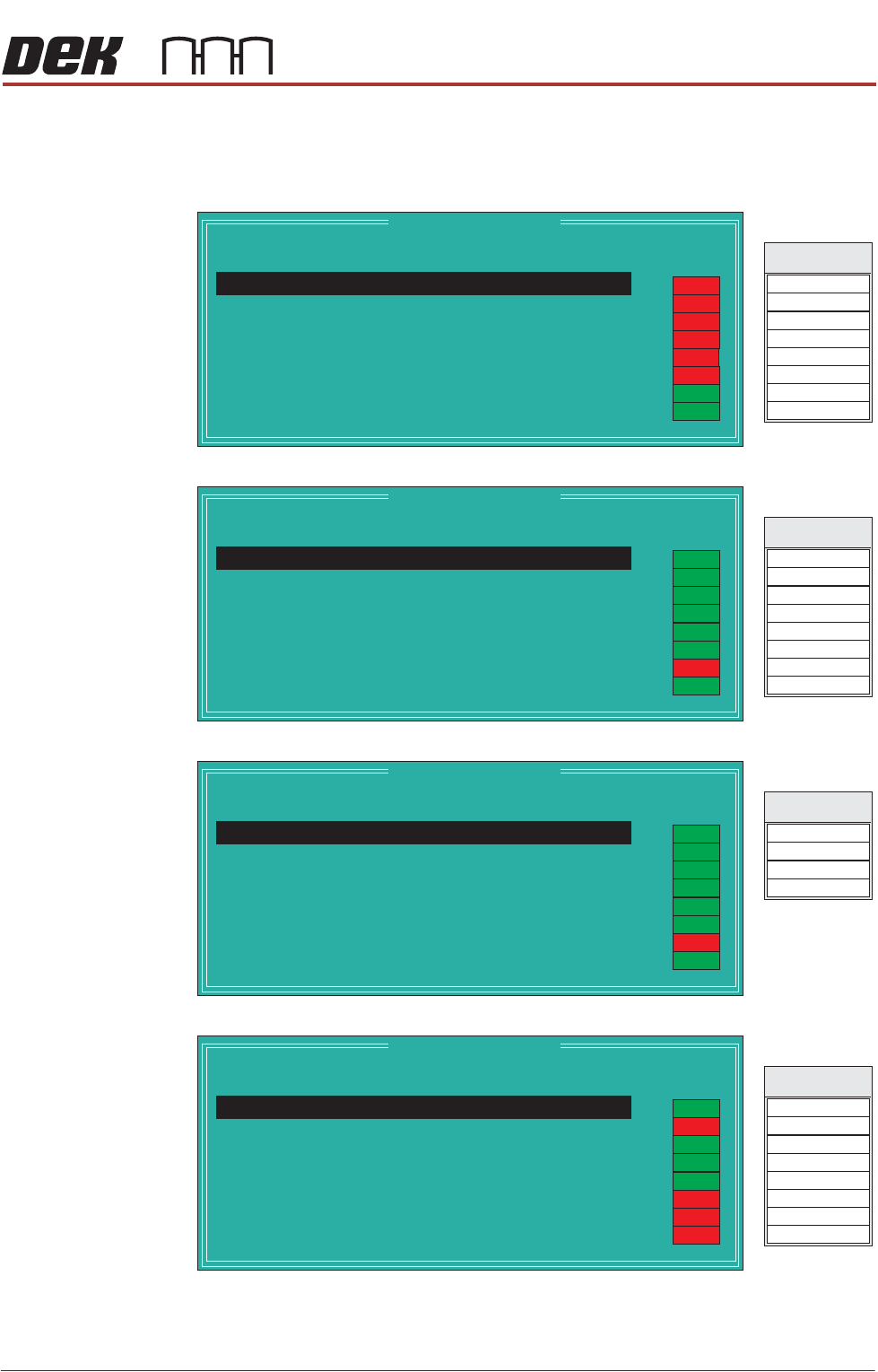
DIAGNOSTI CS SYSTEM 39.4 Technical Reference Manual Chapter Issue 4, Aug 14 Node 2 Group 0 Node 2 Group 1 Node 2 Group 2 Node 3 Group 0 Node 2 Group 0 Point Description --------------------- --------- ------- Bit No Sens…
DIAGNOSTICS
SYSTEM
Chapter Issue 4, Aug 14 Technical Reference Manual 39.3
2. Some of the Point Description titles may vary dependant on options fitted to
the printer.
Node 1 Group 0
Node 1 Group 1
Node 1 Group 2
Node 1 Group 3
Node 1 Group 0
Point Description
---------------------
---------
-------
Bit No
Sense
-----------
------
Direction
State
Not Used
Not Used
Front Squeegee Home
Rear Squeegee Home
Moving Rail Home
Rail Lifted Left
Rail Lifted Right
1
2
3
4
5
6
7
Positive
Positive
Positive
Positive
Positive
Negative
Negative
Input
Input
Input
Input
Input
Input
Input
OFF
ON
OFF
OFF
OFF
OFF
DIG IN 0
DIG IN 4
DIG IN 1
Signal
DIG IN 5
DIG IN 6
DIG IN 2
DIG IN 3
DIG IN 7
OFF
ON
Not Used 0
Positive
Input
Node 1 Group 1
Point Description
---------------------
---------
-------
Bit No
Sense
-----------
------
Direction
State
Board Stop In
Board At Left
Board At Right
Left Jog Button
Right Jog Button
Power On Monitor
Cover Interlock
1
2
3
4
5
6
7
Negative
Negative
Negative
Positive
Positive
Positive
Negative
Input
Input
Input
Input
Input
Input
Input
OFF
DIG IN 8
DIG IN 12
DIG IN 9
Signal
DIG IN 13
DIG IN 14
DIG IN 10
DIG IN 11
DIG IN 15
ON
Board At Stop
0
Negative
Input
ON
ON
ON
ON
ON
ON
Node 1 Group 2
Point Description
---------------------
---------
-------
Bit No
Sense
-----------
------
Direction
State
Downline Ready A
Not Used
Not Used
1
2
3
Positive
Positive
Negative
Input
Input
Input
OFF
DIG IN 16
DIG IN 17
Signal
DIG IN 18
DIG IN 19
ON
Upline Ready A
0
Positive
Input
ON
ON
ON
ON
ON
ON
Node 1 Group 3
Point Description
---------------------
---------
-------
Bit No
Sense
-----------
------
Direction
State
Trigger Image Capture
Belt Motors Power
Belt Motors Direction
HTC Enable
MIU Send Upline A
MIU Send Downline A
MIU Available Out A
1
2
3
4
5
6
7
Negative
Positive
Positive
Positive
Positive
Positive
Positive
Output
Output
Output
Output
Output
Output
Output
OFF
DIG OUT 0
DIG OUT 4
DIG OUT 1
Signal
DIG OUT 5
DIG OUT 6
DIG OUT 2
DIG OUT 3
DIG OUT 7
Servo Amp Enable
0
Positive
Output
ON
ON
ON
ON
OFF
OFF
OFF
DIAGNOSTICS
SYSTEM
39.4 Technical Reference Manual Chapter Issue 4, Aug 14
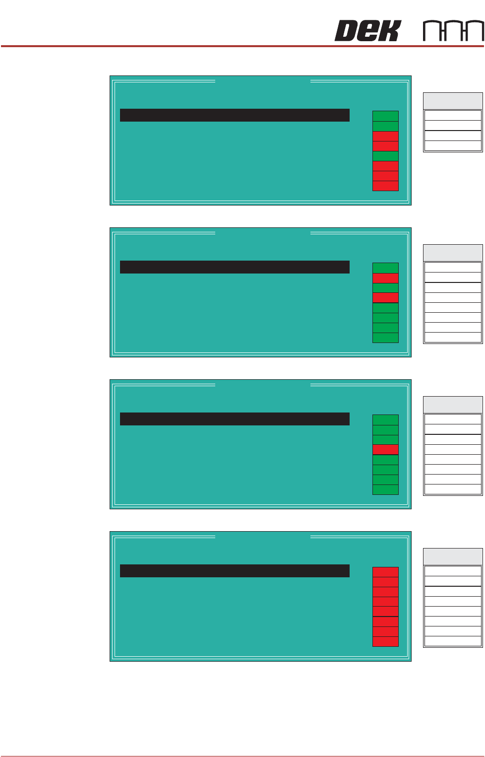
Node 2 Group 0
Node 2 Group 1
Node 2 Group 2
Node 3 Group 0
Node 2 Group 0
Point Description
---------------------
---------
-------
Bit No
Sense
-----------
------
Direction
State
Lid Bolt Shut
Vacuum Tooling Sensor
Screen Present
1
2
3
Negative
Negative
Negative
Input
Input
Input
OFF
DIG IN 0
DIG IN 1
Signal
DIG IN 2
DIG IN 3
Air Pressure
0
Negative
Input
ON
ON
ON
OFF
OFF
OFF
OFF
Node 2 Group 1
Point Description
---------------------
---------
-------
Bit No
Sense
-----------
------
Direction
State
Green Beacon
Amber Beacon
Red Beacon
Buzzer
Release Table Brake
Paste Roll Lamp
Chase Clamp
1
2
3
4
5
6
7
Negative
Negative
Negative
Negative
Negative
Negative
Negative
Output
Output
Output
Output
Output
Output
Output
DIG OUT 0
DIG OUT 4
DIG OUT 1
Signal
DIG OUT 5
DIG OUT 6
DIG OUT 2
DIG OUT 3
DIG OUT 7
ON
Vacuum Valve
0
Negative
Output
ON
ON
ON
ON
OFF
OFF
ON
Node 2 Group 2
Point Description
---------------------
---------
-------
Bit No
Sense
-----------
------
Direction
State
Clamp Board
Board Stop
Lid Bolt
Down-line Board Stop
Solvent Tank Press
Cleaner Blade
Not Used
1
2
3
4
5
6
7
Negative
Negative
Negative
Negative
Negative
Negative
Negative
Output
Output
Output
Output
Output
Output
Output
DIG OUT 8
DIG OUT 12
DIG OUT 9
Signal
DIG OUT 13
DIG OUT 14
DIG OUT 10
DIG OUT 11
DIG OUT 15
ON
Screen Clamp
0
Negative
Output
ON
ON
ON
ON
OFF
ON
ON
Node 3 Group 0
Point Description
---------------------
---------
-------
Bit No
Sense
-----------
------
Direction
State
ProFlow Cassette Low
Roll Height Monitor Rec
Screen at Rear
Screen Stop Extended
Screen Stop Retracted
Drip Tray Retracted
Cartridge Away
1
2
3
4
5
6
7
Negative
tive
tive
tive
tive
tive
tive
Nega
Nega
Nega
Nega
Nega
Nega
Input
Input
Input
Input
Input
Input
Input
DIG IN 0
DIG IN 4
DIG IN 1
Signal
DIG IN 5
DIG IN 6
DIG IN 2
DIG IN 3
DIG IN 7
ProFlow Fitted
0
Negative
Input
OFF
OFF
OFF
OFF
OFF
OFF
OFF
OFF
DIAGNOSTICS
SYSTEM
Chapter Issue 4, Aug 14 Technical Reference Manual 39.5
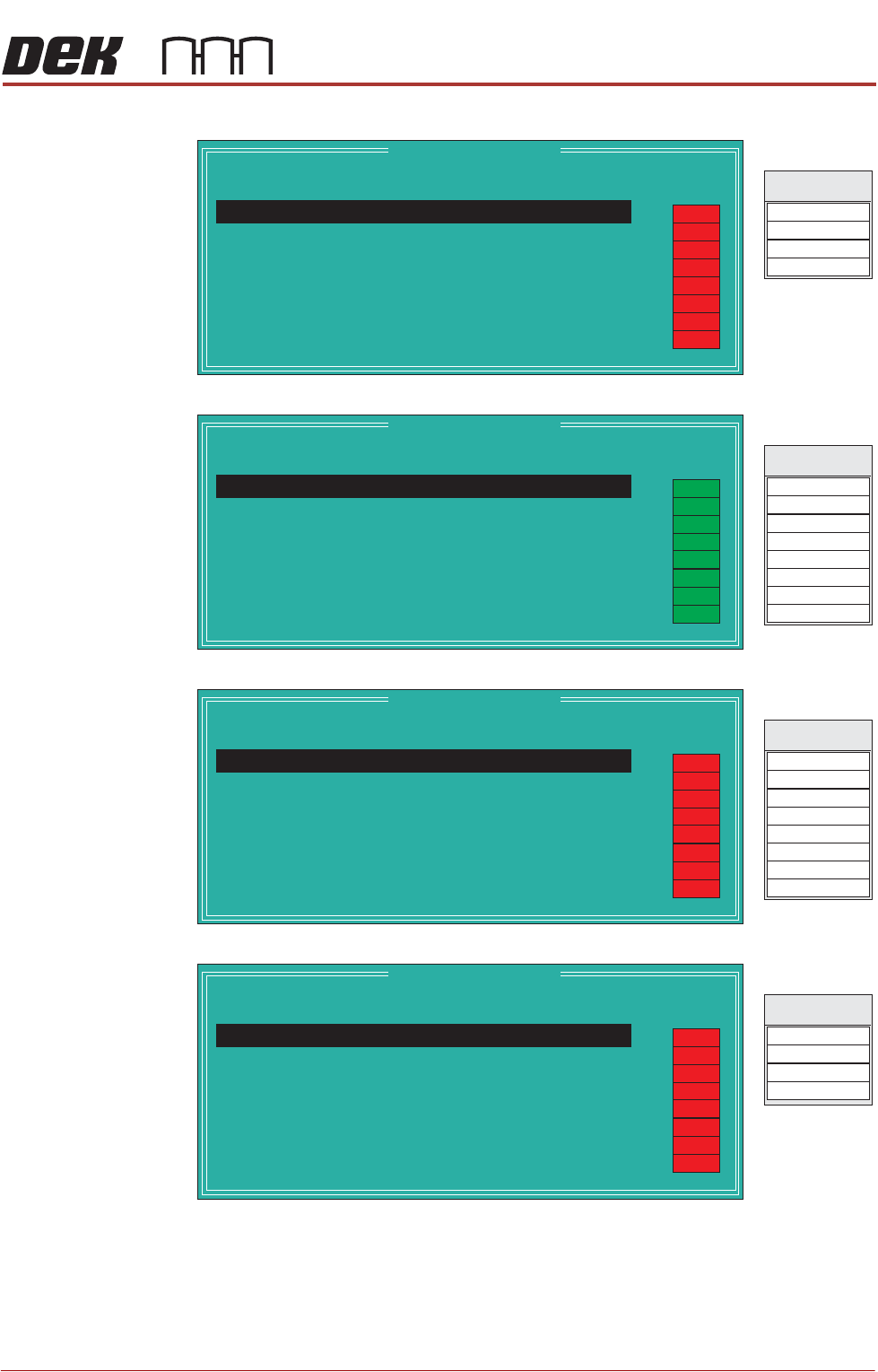
Node 3 Group 1
Node 3 Group 2
Node 4 Group 0
Node 4 Group 1
Node 3 Group 1
Point Description
---------------------
---------
-------
Bit No
Sense
-----------
------
Direction
State
Cartridge Empty
Not Used
Not Used
1
2
3
Nega
Nega
Nega
tive
tive
tive
Input
Input
Input
OFF
DIG IN 8
DIG IN 9
Signal
DIG IN 10
DIG IN 11
Cartridge Home
0
Positive
Input
OFF
OFF
OFF
OFF
OFF
OFF
OFF
Node 3 Group 2
Point Description
---------------------
---------
-------
Bit No
Sense
-----------
------
Direction
State
Not Used
Not Used
ProFlow Reg Control
Dispense Paste
Tilt Cartridge Away
Drip Tray Actuator
Screen Stop Actuator
1
2
3
4
5
6
7
Negative
Negative
Negative
Negative
Negative
Negative
Negative
Output
Output
Output
Output
Output
Output
Output
DIG OUT 0
DIG OUT 4
DIG OUT 1
Signal
DIG OUT 5
DIG OUT 6
DIG OUT 2
DIG OUT 3
DIG OUT 7
Roll Height Monitor Las
0
Negative
Output
ON
ON
ON
ON
ON
ON
ON
ON
Node 4 Group 0
Point Description
---------------------
---------
-------
Bit No
Sense
-----------
------
Direction
State
Paper Low
Cleaning Unit Home
USC Vacuum Sense
Levelness Screen Sense
Levelness Cylinder Ext
Not Used
Not Used
1
2
3
4
5
6
7
Nega
Nega
Nega
Nega
Nega
Nega
tive
Positive
tive
tive
tive
tive
tive
Input
Input
Input
Input
Input
Input
Input
DIG IN 0
DIG IN 4
DIG IN 1
Signal
DIG IN 5
DIG IN 6
DIG IN 2
DIG IN 3
DIG IN 7
Solvent Low
0
Negative
Input
OFF
OFF
OFF
OFF
OFF
OFF
OFF
OFF
Node 4 Group 1
Point Description
---------------------
---------
-------
Bit No
Sense
-----------
------
Direction
State
Not Used
Cleaner Dropped
Not Used
1
2
3
Nega
Nega
Nega
tive
tive
tive
Input
Input
Input
DIG IN 8
DIG IN 9
Signal
DIG IN 10
DIG IN 11
Not Used
0
Negative
Input
OFF
OFF
OFF
OFF
OFF
OFF
OFF
OFF