88192277-01-19 - Micron Technical Reference V9 Volume 4.pdf - 第223页
TRANSPORTATION - MAJOR RELOCATION TRANSIT BRACKETS AND SCREWS REMOVAL Chapter Issue 5, Nov 19 Technical Reference Manual 42.57 Grease Protection Before the machin e was packaged, some areas within the machine were coated…
TRANSPORTATION - MAJOR RELOCATION
TRANSIT BRACKETS AND SCREWS REMOVAL
42.56 Technical Reference Manual Chapter Issue 5, Nov 19
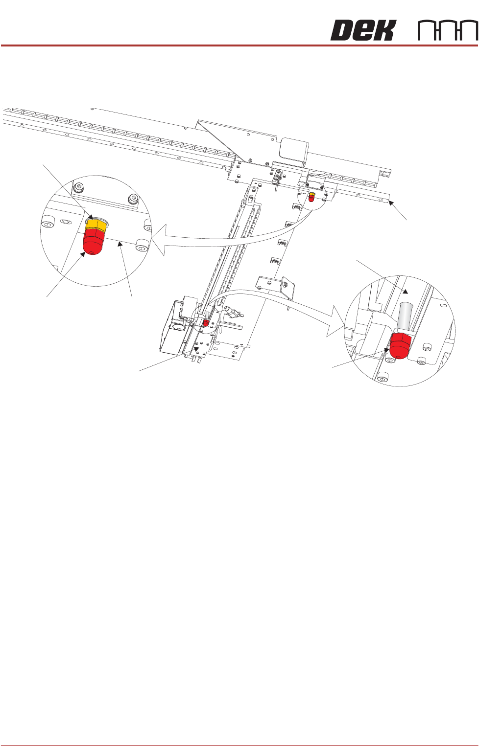
Camera Transit
Screws (Linear
Drive)
1. Loosen the lock nut that secures the transit screw to the camera Y plate.
2. Remove the transit screw that secures the camera Y plate to the camera Y
linear bearing ensuring that the lock nut and crinkle washer are removed
with the transit screw.
3. Remove the transit screw that secures the camera X drag chain bracket to
the camera beam extrusion.
Under Stencil
Cleaner
Snip the red cable ties securing the piece of card to the top of the under stencil
cleaner. Remove the cable ties and the piece of card from the machine.
This concludes the transit bracket and screw removal procedure. Transit brack-
ets, screws and associated fasteners should be stored for future reuse.
View on Right Hand Underside of Camera Beam
Transit Screw
Transit Screw
Camera Y Plate
Camera Y Linear Bearing
Camera X Drag Chain Bracket
Camera Beam Extrusion
Lock Nut and
Crinkle Washer
TRANSPORTATION - MAJOR RELOCATION
TRANSIT BRACKETS AND SCREWS REMOVAL
Chapter Issue 5, Nov 19 Technical Reference Manual 42.57
Grease Protection Before the machine was packaged, some areas within the machine were coated
with LM grease or multi purpose oil to protect the metal surfaces from corroding
during transportation.
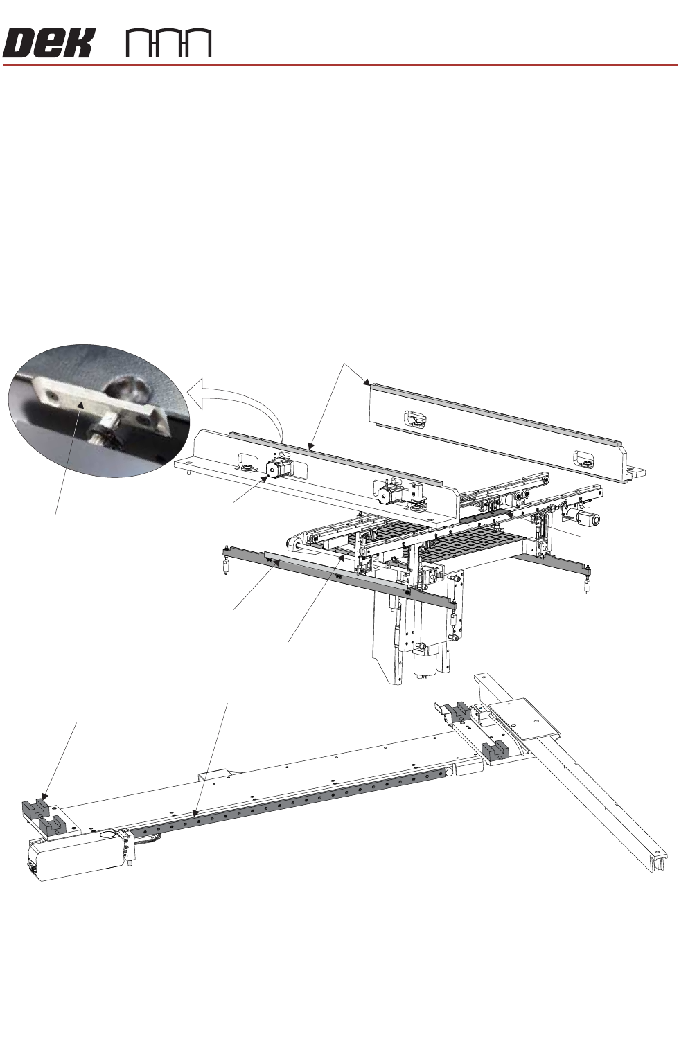
Using a lint free cloth, remove any surplus grease from the following areas,
ensuring that a light coating remains:
• Print carriage linear bearing guides (above the printheads)
• Camera linear bearing guides (below the printheads)
• Rear moving rail linear bearing guides (either side of the rising table)
• Top face of both clatter bars (either side of the rising table)
• Actuator striker plates (in 3 positions)
Figure 42-20 Grease Protection
Print Carriage Linear Bearing Guides
Moving Rail Linear Bearing Guide (in 2 positions)
Clatter Bar (in 2 positions)
Board Clamp
(in 2 positions)
Camera Linear Bearing GuideX
Camera Linear Bearing GuideY
(4 Positions)
Actuator (in 3 positions)
Actuator Striker Plate
(in 3 positions)
TRANSPORTATION - MAJOR RELOCATION
TRANSIT BRACKETS AND SCREWS REMOVAL
42.58 Technical Reference Manual Chapter Issue 5, Nov 19
WARNING
BOARD CLAMPS. EXTREME CARE MUST BE EXERCISED WHEN WORKING IN
THE TOOLING AREA OF THE MACHINE TO AVOID INJURY. THE FOILS ON THE
FRONT AND REAR BOARD CLAMPS ARE VERY SHARP.
The front and rear board clamp foils are greased for protection during transpor-
tation. This grease protection must to be removed completely using a lint free
cloth.
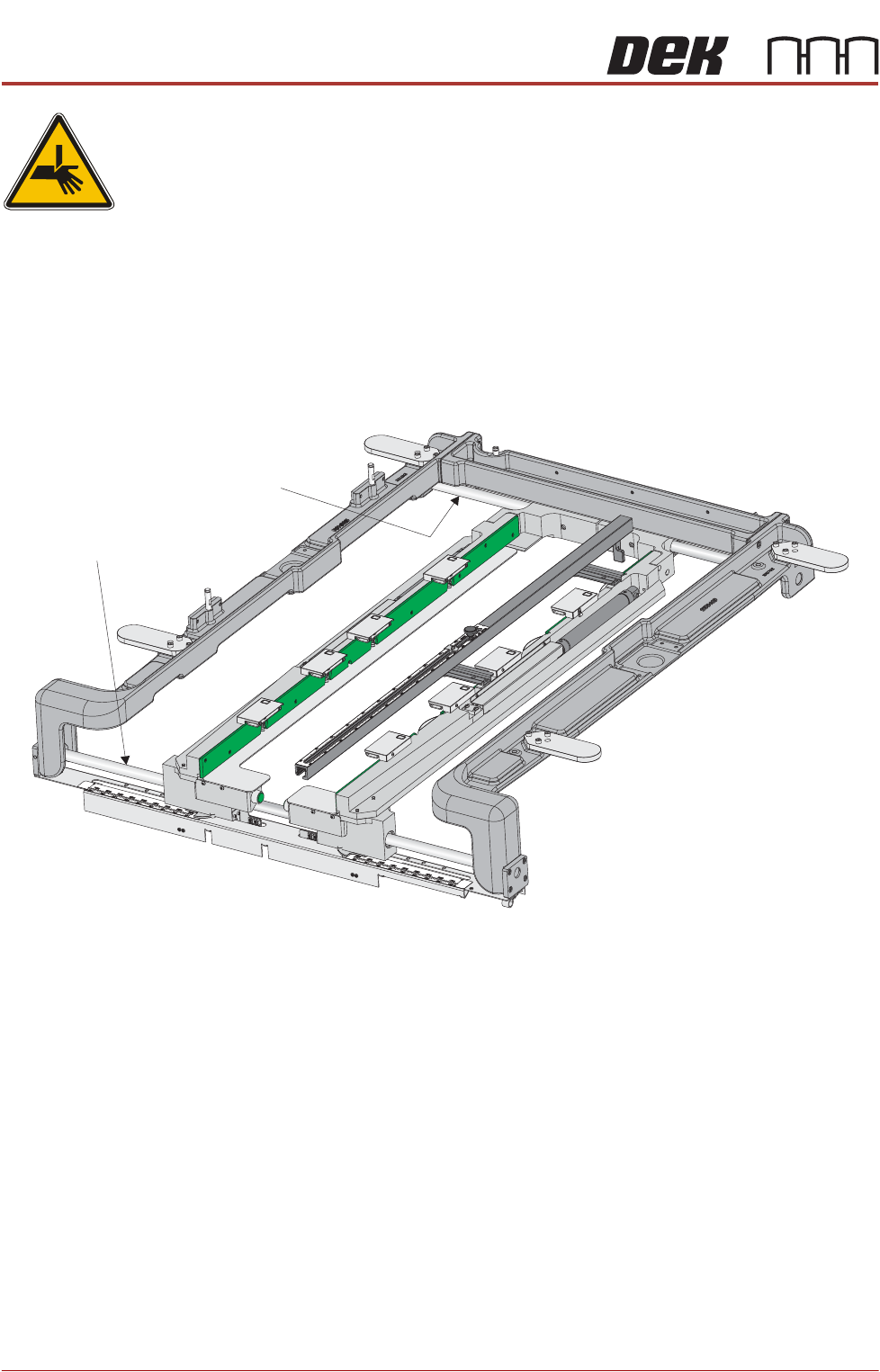
ASM Chase The front and rear guide bars are coated with multi purpose oil for transporta-
tion. Using a lint free cloth, thoroughly wipe the bars to remove the oil com-
pletely.
Figure 42-21 Grease Protection - ASM
Front Guide Bar
Rear Guide Bar