88192277-01-19 - Micron Technical Reference V9 Volume 4.pdf - 第150页
TRANSPORTATION - MINOR RELOCATION TRANSPORTING THE MACHINE 41.8 Technical Reference Manual Chapter Issue 4, May 19 TRANSPORTING THE MACHINE W ARNING MACHINE LIFTING. TO PREVENT SERIOU S INJUR Y TO PERSONNEL, DURING LIFTI…

TRANSPORTATION - MINOR RELOCATION
TRANSIT BRACKET INSTALLATION
Chapter Issue 4, May 19 Technical Reference Manual 41.7
7. Tighten the nylon screws (5) on to the carriage rail.
TRANSPORTATION - MINOR RELOCATION
TRANSPORTING THE MACHINE
41.8 Technical Reference Manual Chapter Issue 4, May 19
TRANSPORTING THE MACHINE
WARNING
MACHINE LIFTING. TO PREVENT SERIOUS INJURY TO PERSONNEL, DURING
LIFTING AND TRANSPORTATION OPERATIONS, ENSURE THE MACHINE IS
LIFTED AND TRANSPORTED IN ACCORDANCE WITH INSTRUCTIONS DETAILED
IN THIS SECTION.
NOTE
Damage to the machine will occur if the machine is lifted:
• Using lifting strops
OR . . .
• From the sides
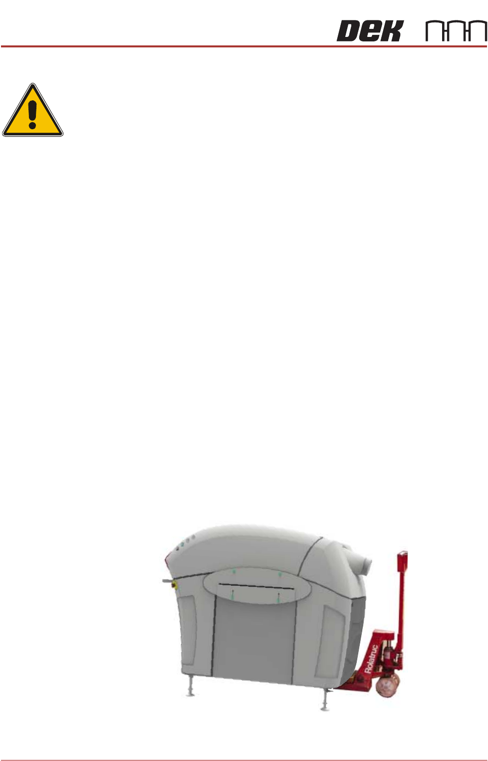
The machine may be lifted using a pallet truck or similar manually operated
machine that meets the following criteria:
• Minimum fork length of 1219mm (48 inches)
• Fork span >686mm (27 inches) and <914mm (36 inches)
• Fork Height (thickness) <50mm (2 inches)
• Lifting capability of 2000kg
1. Locate the forks under the machine base so the weight of the machine is
taken evenly on the front and rear cross members.
NOTE
Height of machine feet may have to be adjusted to allow the pallet truck to
raise the machine clear of the floor.
2. Raise the machine and carefully transport into position.
Figure 41-4 Machine on Pallet Truck
TRANSPORTATION - MINOR RELOCATION
TRANSIT BRACKET REMOVAL
Chapter Issue 4, May 19 Technical Reference Manual 41.9
TRANSIT BRACKET REMOVAL
To remove the transit brackets and screws from the machine, remove/open the
rear printhead cover. On sliding cover machines remove the two upper side
panels as detailed in the Covers chapter.
Chase Transit
Brackets
The chase transit brackets include the following:
• Front Transit Bracket
• Rear Transit Bracket
• Rear Chase Transit Bracket
• Cover Frame Transit Bracket
The Front and Rear Transit Bracket Location and Rear Chase Transit Bracket
Location figures earlier in this chapter refers.
The following procedure must be adhered to and care must be taken to ensure
that the chase/ASM is released in a controlled manner to prevent damage to
the roller bearings or the actuators.
To remove the chase transit brackets, carry out the following procedure:
NOTE
The numbers in brackets refer to the items in the Chase Transit Brackets, Rear
Chase Transit Bracket and Cover Frame Bracket figures earlier in this chapter.
1. Using a 13mm spanner, loosen the four M8 nuts (3) directly below the front
and rear transit brackets (2).
2. Slowly loosen the four M8 nuts (3) above the front and rear transit brackets
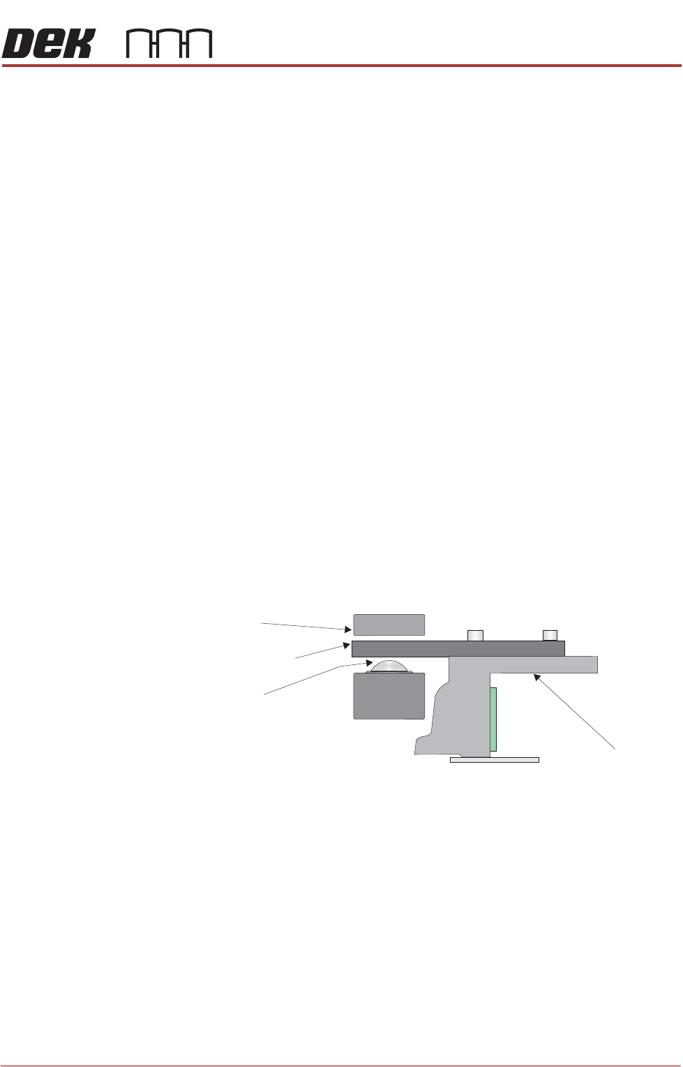
(2) to lower the roller counter plates onto the roller bearings.
3. Using a 4mm Allen key, remove the M5 cap head screws (9) and washers
(10) that attach the adaptor bracket (8) at each end of the front and rear
transit brackets (2) to the left and right printheads.
4. Remove the four M8 nuts (3) and washers (4) above the front and rear transit
brackets (2).
5. Remove the front and rear transit brackets (2) from the M8 chase studs (1).
6. Loosen the transit adjustment screw lock nut (6) on the front and rear transit
brackets (2).
7. Loosen the transit adjustment screw lock nut (15) on the rear chase transit
bracket (12).
8. Using a 6mm Allen key, loosen the transit adjustment screw (7), on both the
left chase transit brackets (5), and the transit adjustment screw (11) on the
rear chase transit bracket (12), so that the chase comes into contact with
Chase
Chase Clamp
Roller Bearing
Roller Counter Plate