88192277-01-19 - Micron Technical Reference V9 Volume 4.pdf - 第169页
TRANSPORTATION - MAJOR RELOCATION PREPARATION Chapter Issue 5, Nov 19 Technical Reference Manual 42.3 ASM Chase Coat the front and rear guide bars of t he ASM with multi purpose oil. Figure 42-2 Grease Protection - ASM F…
TRANSPORTATION - MAJOR RELOCATION
PREPARATION
42.2 Technical Reference Manual Chapter Issue 5, Nov 19
Grease Protection
WARNING
BOARD CLAMPS. EXTREME CARE MUST BE EXERCISED WHEN WORKING IN
THE TOOLING AREA OF THE MACHINE TO AVOID INJURY. THE FOILS ON THE
FRONT AND REAR BOARD CLAMPS ARE VERY SHARP.
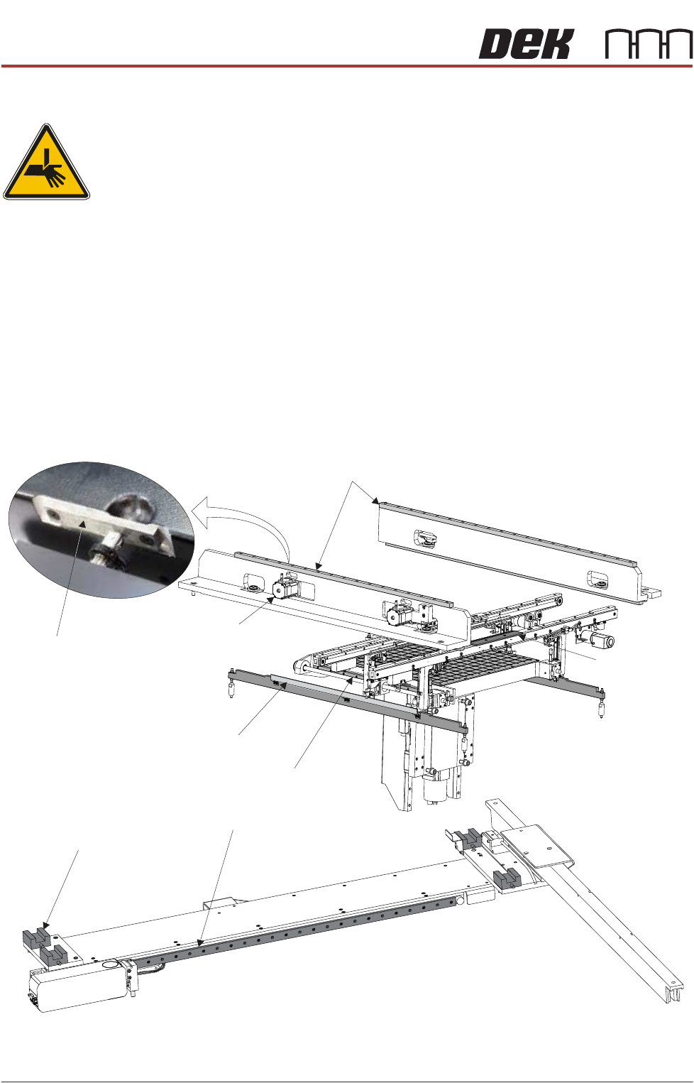
If the machine is being relocated to another site or placed into storage, bare
metal surfaces must be greased to protect against corrosion. Using a small
brush or cloth, apply LM grease to the following areas:
• Print carriage linear bearing guides (above the printheads)
• Camera linear bearing guides (below the printheads)
• Rear moving rail linear bearing guides (either side of the rising table)
• Top face of both clatter bars (either side of the rising table)
• Actuator striker plates (in 3 positions)
• Front and rear board clamps
Figure 42-1 Grease Protection
Print Carriage Linear Bearing Guides
Moving Rail Linear Bearing Guide (in 2 positions)
Clatter Bar (in 2 positions)
Board Clamp
(in 2 positions)
Camera Linear Bearing GuideX
Camera Linear Bearing GuideY
(4 Positions)
Actuator (in 3 positions)
Actuator Striker Plate
(in 3 positions)
TRANSPORTATION - MAJOR RELOCATION
PREPARATION
Chapter Issue 5, Nov 19 Technical Reference Manual 42.3
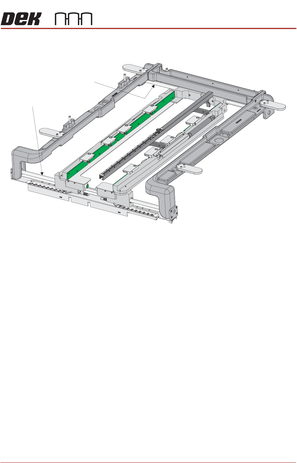
ASM Chase Coat the front and rear guide bars of the ASM with multi purpose oil.
Figure 42-2 Grease Protection - ASM
Front Guide Bar
Rear Guide Bar
TRANSPORTATION - MAJOR RELOCATION
TRANSIT BRACKET AND SCREW INSTALLATION
42.4 Technical Reference Manual Chapter Issue 5, Nov 19
TRANSIT BRACKET AND SCREW INSTALLATION
NOTE
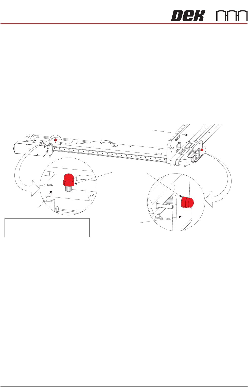
Transit brackets and screws are red in colour for easy identification.
Under Stencil
Cleaner
1. Place a piece of card (300mm by 180mm approximately) onto the top of the
stencil cleaner.
2. Join three large red cable ties together and secure the card and the cleaner
to the carriage by fitting them around the whole cleaner assembly.
Camera Transit
Screws (Rotary
Drive)
1. Manually pull the camera beam to the front of the machine.
2. Align the threaded hole in the camera Y drag chain bracket with the hole in
the right hand printhead and fit the M8 transit screw.
3. Align the threaded hole in the camera beam with the hole in the camera X
drag chain bracket (below the camera beam) and fit the M8 transit screw
downwards through the camera beam.
Note
Camera X Drag Chain Bracket is hidden
from view by the Camera Beam
Transit Screws
Camera Beam
Right Hand Printhead
Camera Y Drag
Chain Bracket