88192277-01-19 - Micron Technical Reference V9 Volume 4.pdf - 第224页
TRANSPORTATION - MAJOR RELOCATION TRANSIT BRACKETS AND SCREWS REMOVAL 42.58 Technical Reference Manual Chapter Issue 5, Nov 19 W ARNING BOARD CLAMPS. EXTREME CA RE MUST BE EXERCIS ED WHEN WORKING IN THE TOOLING AREA OF T…
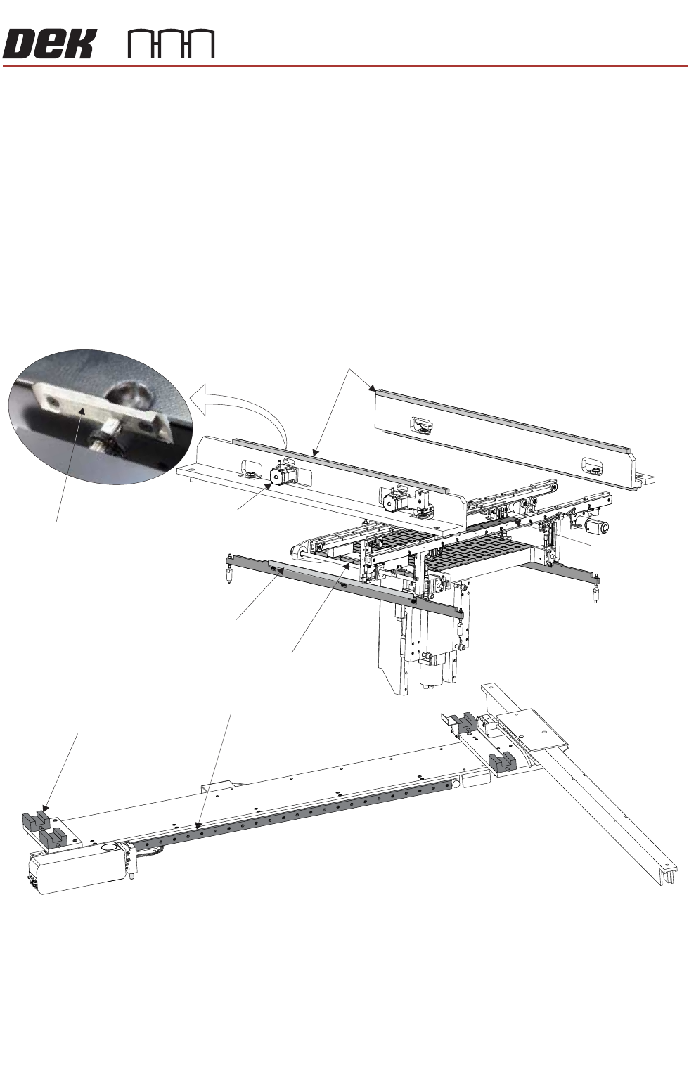
TRANSPORTATION - MAJOR RELOCATION
TRANSIT BRACKETS AND SCREWS REMOVAL
Chapter Issue 5, Nov 19 Technical Reference Manual 42.57
Grease Protection Before the machine was packaged, some areas within the machine were coated
with LM grease or multi purpose oil to protect the metal surfaces from corroding
during transportation.
Using a lint free cloth, remove any surplus grease from the following areas,
ensuring that a light coating remains:
• Print carriage linear bearing guides (above the printheads)
• Camera linear bearing guides (below the printheads)
• Rear moving rail linear bearing guides (either side of the rising table)
• Top face of both clatter bars (either side of the rising table)
• Actuator striker plates (in 3 positions)
Figure 42-20 Grease Protection
Print Carriage Linear Bearing Guides
Moving Rail Linear Bearing Guide (in 2 positions)
Clatter Bar (in 2 positions)
Board Clamp
(in 2 positions)
Camera Linear Bearing GuideX
Camera Linear Bearing GuideY
(4 Positions)
Actuator (in 3 positions)
Actuator Striker Plate
(in 3 positions)
TRANSPORTATION - MAJOR RELOCATION
TRANSIT BRACKETS AND SCREWS REMOVAL
42.58 Technical Reference Manual Chapter Issue 5, Nov 19
WARNING
BOARD CLAMPS. EXTREME CARE MUST BE EXERCISED WHEN WORKING IN
THE TOOLING AREA OF THE MACHINE TO AVOID INJURY. THE FOILS ON THE
FRONT AND REAR BOARD CLAMPS ARE VERY SHARP.
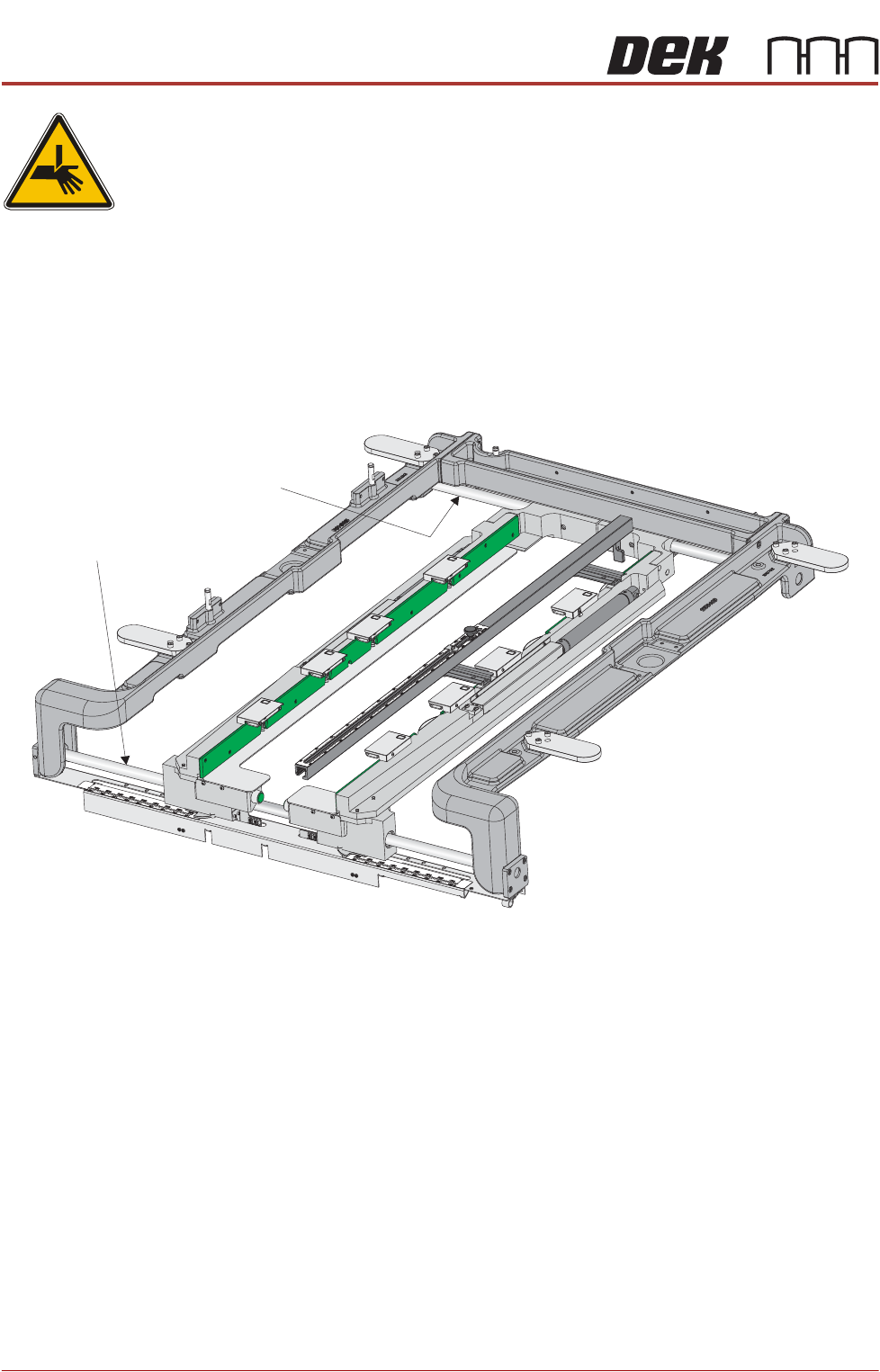
The front and rear board clamp foils are greased for protection during transpor-
tation. This grease protection must to be removed completely using a lint free
cloth.
ASM Chase The front and rear guide bars are coated with multi purpose oil for transporta-
tion. Using a lint free cloth, thoroughly wipe the bars to remove the oil com-
pletely.
Figure 42-21 Grease Protection - ASM
Front Guide Bar
Rear Guide Bar
TRANSPORTATION - MAJOR RELOCATION
MACHINE HEIGHT AND LEVELLING
Chapter Issue 5, Nov 19 Technical Reference Manual 42.59
MACHINE HEIGHT AND LEVELLING
Leg Spacers
(Camera Linear
Drive Machine
Only)
The mounting feet on the camera linear drive machine must be kept as short as
possible to reduce vibration and oscillation.
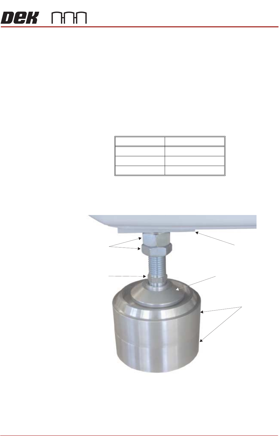
To achieve the height required, 8 leg spacers (maximum of two per foot) are
supplied. The leg spacers interlock together and the machine foot locates in the
recess of the top leg spacer.
1. Using the table below, determine the amount of leg spacers to achieve the
required machine height:
NOTE
The amount of exposed thread of the machine leg should be kept to a
minimum to ensure machine accuracy remains within limits.
2. Place the correct number of leg spacers under each mounting foot. Do not
place leg spacers under the centre rear mounting foot. Lower the machine
ensuring that each foot is located inside the recessed top, figure below
refers.
NOTE
Do not attempt to manoeuvre the machine into position whilst mounted on
the leg spacers. The machine must be lifted, moved and lowered ensuring
that the leg spacers are moved with the machine.
Transport Height Leg Spacers Required
840mm - 895mm 0
896mm - 940mm 1
941mm - 980mm 2
Leg Spacers
(2 shown)
Machine Mounting Foot
M24 Locking Nuts
Machine Frame
Leg Adjusting Nut