88192277-01-19 - Micron Technical Reference V9 Volume 4.pdf - 第195页
TRANSPORTATION - MAJOR RELOCATION DISMANTLING THE MACHINE Chapter Issue 5, Nov 19 Technical Reference Manual 42.29 2. Disconnect the following from th e left hand auxiliary conveyor: • M27PL07 from M27SK07 on the rear ra…
TRANSPORTATION - MAJOR RELOCATION
DISMANTLING THE MACHINE
42.28 Technical Reference Manual Chapter Issue 5, Nov 19
High Throughput
Conveyors (HTC)
The high throughput conveyors (HTC) auxiliary conveyors must be removed
prior to transportation.
1. Disconnect the following from the right hand auxiliary conveyor:
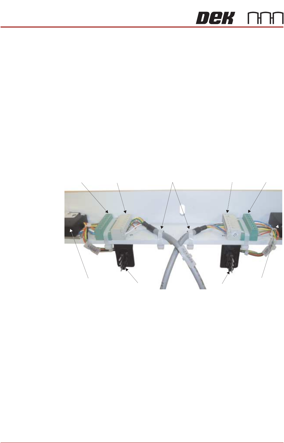
• M27PL17 from M27SK17 on the rear rail
• M27PL16 from M27SK16 on the front rail
• M27PL14 from M27SK14 on the front rail and unclip M27SK14 from its
bracket
• Electrical connection from M27SOL01 (pneumatic solenoid) on the front
rail
• Electrical connection from M27SOL03 (pneumatic solenoid) on the front
rail
• Pneumatic feed from the input connector of M27SOL03
• 8SK21 from 8PL21 and 8SK23 from 8PL23 of the belt speed motor
controllers
• M27SK24 from M27PL24 and M27SK25 from M27PL25 of the belt speed
motor controllers. Cut the two cable ties.
NOTE
Some cable ties need cutting to separate cables that are attached to the
auxiliary rail and those that stay in the machine.
M27PL24 M27SK24 M27SK25 M27PL25
8PL21 8PL23
Front Belt Speed
Motor Controller
Rear Belt Speed
Motor Controller
Cable Ties
View on Underside of Right Hand Auxiliary Conveyor Mounting Bracket
TRANSPORTATION - MAJOR RELOCATION
DISMANTLING THE MACHINE
Chapter Issue 5, Nov 19 Technical Reference Manual 42.29
2. Disconnect the following from the left hand auxiliary conveyor:
• M27PL07 from M27SK07 on the rear rail
• M27PL06 from M27SK06 on the front rail
• M27PL05 from M27SK05 on the front rail and unclip M27SK05 from its
bracket
• Electrical connection from M27SOL02 (pneumatic solenoid) on the front
rail
• Pneumatic feed from the input connector of M27SOL02
NOTE
Some cable ties need cutting to separate cables that are attached to the
auxiliary rail and those that stay in the machine.
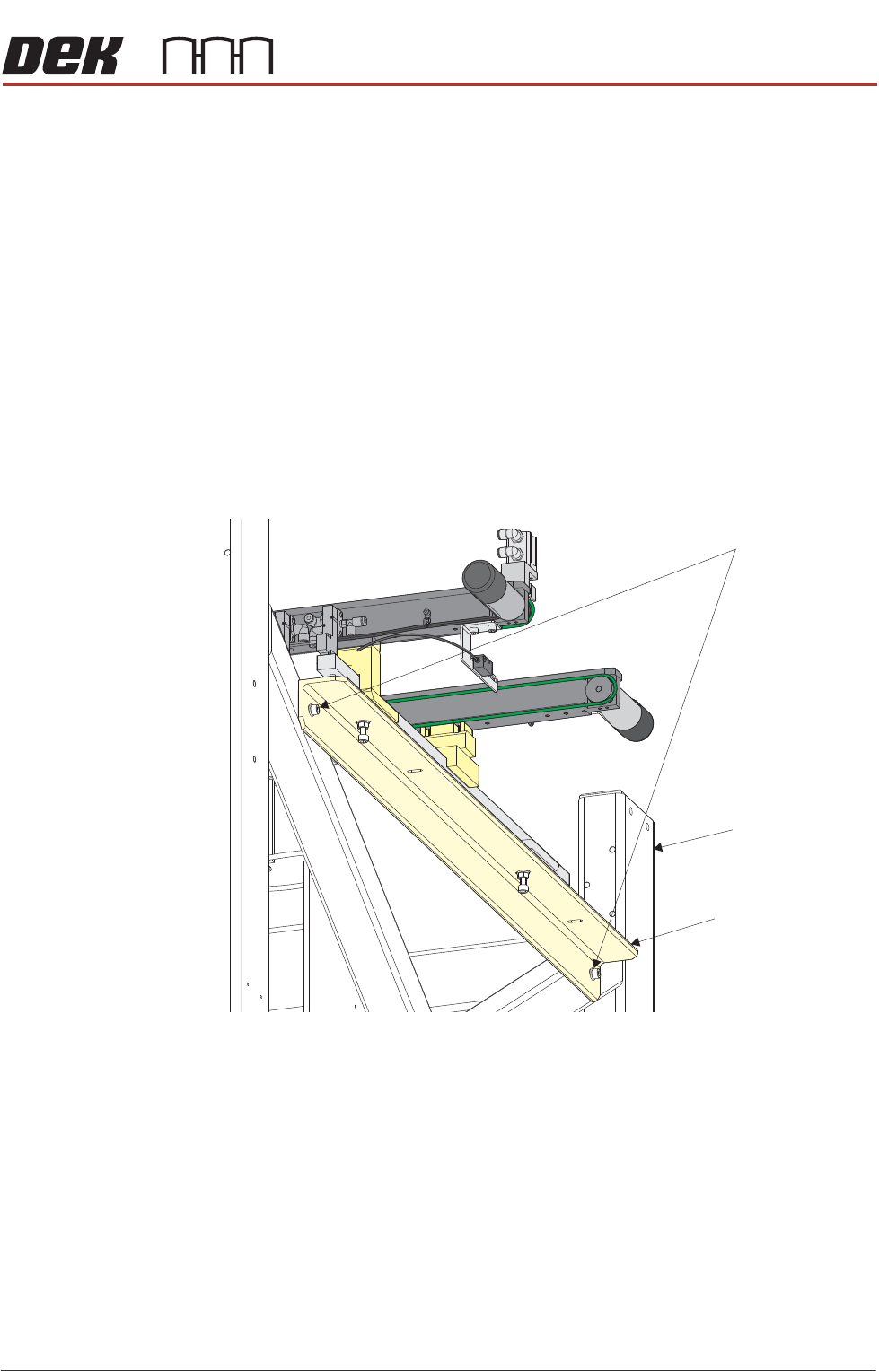
3. Whilst supporting the right hand auxiliary conveyor, remove the two bolts
that secure the auxiliary conveyor mounting bracket to the machine frame.
4. Whilst supporting the left hand auxiliary conveyor, remove the two bolts that
secure the auxiliary conveyor mounting bracket to the machine frame.
5. Place the bolts back into the holes in the machine frame and tighten to
prevent loss during transportation.
6. Fit the side covers and panels that were previously removed.
Using the Covers chapter, remove the left and right safety covers and the
appropriate side panels to gain access to the auxiliary conveyors.
Auxiliary Conveyor Securing Bolts
Auxiliary Conveyor
Mounting Bracket
Machine Frame
TRANSPORTATION - MAJOR RELOCATION
DISMANTLING THE MACHINE
42.30 Technical Reference Manual Chapter Issue 5, Nov 19
Removal of External Solvent Tank
MANDATORY
TOXIC CHEMICALS MAY BE PRESENT. SAFETY GLOVES MUST BE WORN.
MANDATORY
TOXIC CHEMICALS MAY BE PRESENT. EYE PROTECTION MUST BE WORN.
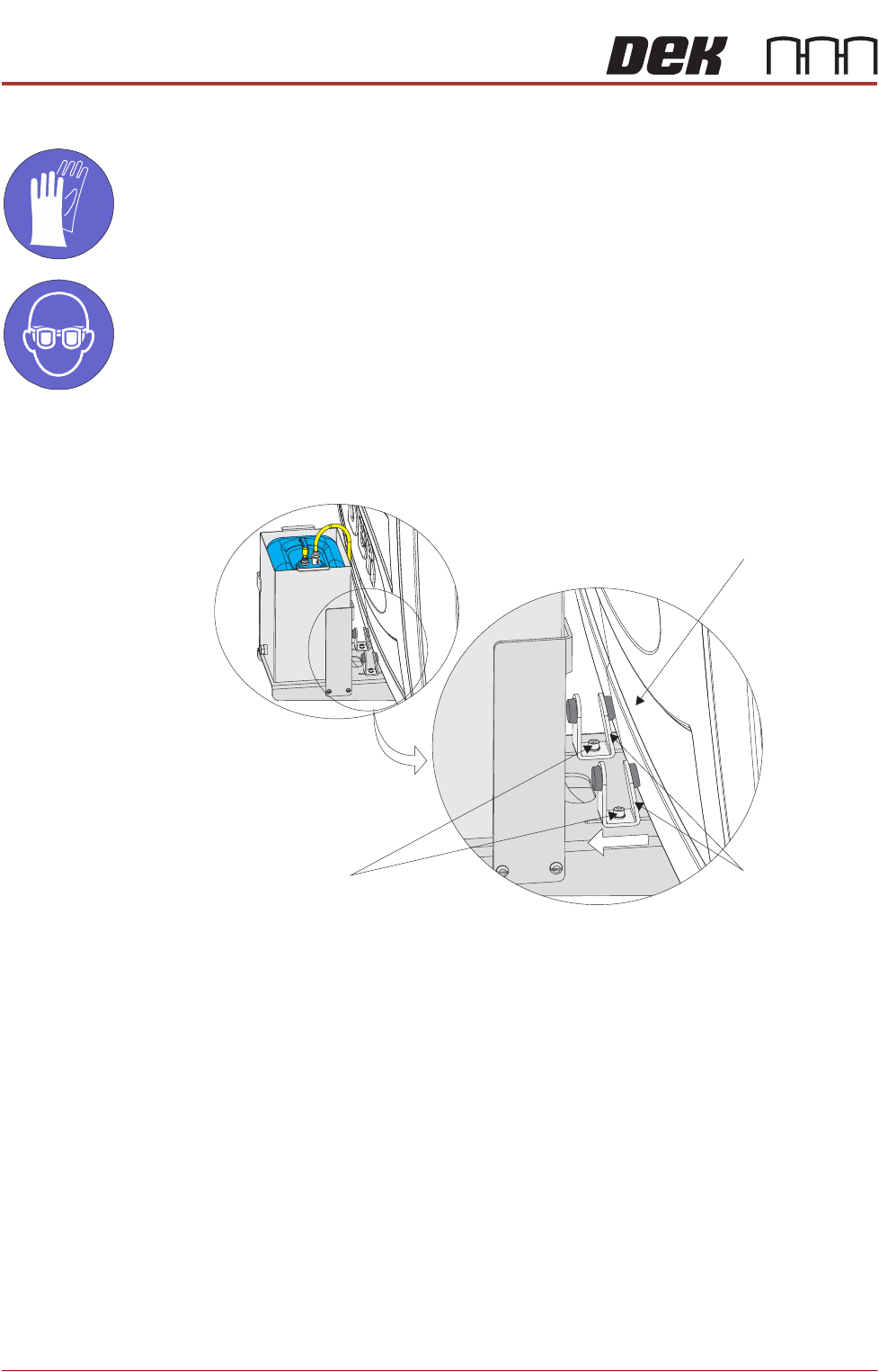
To disconnect and remove the external solvent tank, carry out the following:
1. Loosen the two M5 cap head securing screws and slide the angle brackets
away from the machine cover.
2. Remove the rear panel using the maintenance key.
Machine Cover
Securing Screws
Angle Brackets