00196693-03_UM_SX4DX4_SR706_EN.pdf - 第107页
User Manual SIPLACE SX4/DX4 3 Technical data and assemblies From software version SC.706.xx Version 06/2012 EN 3.3 Dimensions and weight 107 3.3.4 Maneuvering radii for the co mponent trolleys in SX4 machines 3 Fig. 3.3 …
3 Technical data and assemblies User Manual SIPLACE SX4/DX4
3.3 Dimensions and weight From software version SC.706.xx Version 06/2012 EN
106
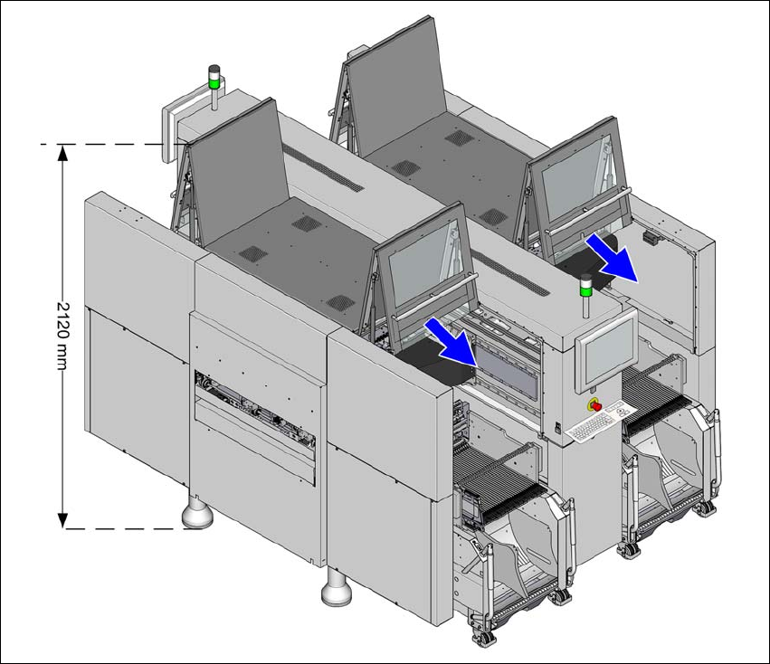
3.3.3 Height of the folded up protective cover
3
Fig. 3.3 - 3 Height of the folded-up protective cover - dimensions in millimeters (example of SX4)
The specified dimensions refer to the max. PCB conveyor height of 950 mm.
(1) The height varies according to the set PCB conveyor height
– for PCB conveyor height 900 mm = 120 mm ± 15 mm
– for PCB conveyor height 930 mm = 150 mm ± 15 mm
– for PCB conveyor height 950 mm = 170 mm ± 15 mm
User Manual SIPLACE SX4/DX4 3 Technical data and assemblies
From software version SC.706.xx Version 06/2012 EN 3.3 Dimensions and weight
107
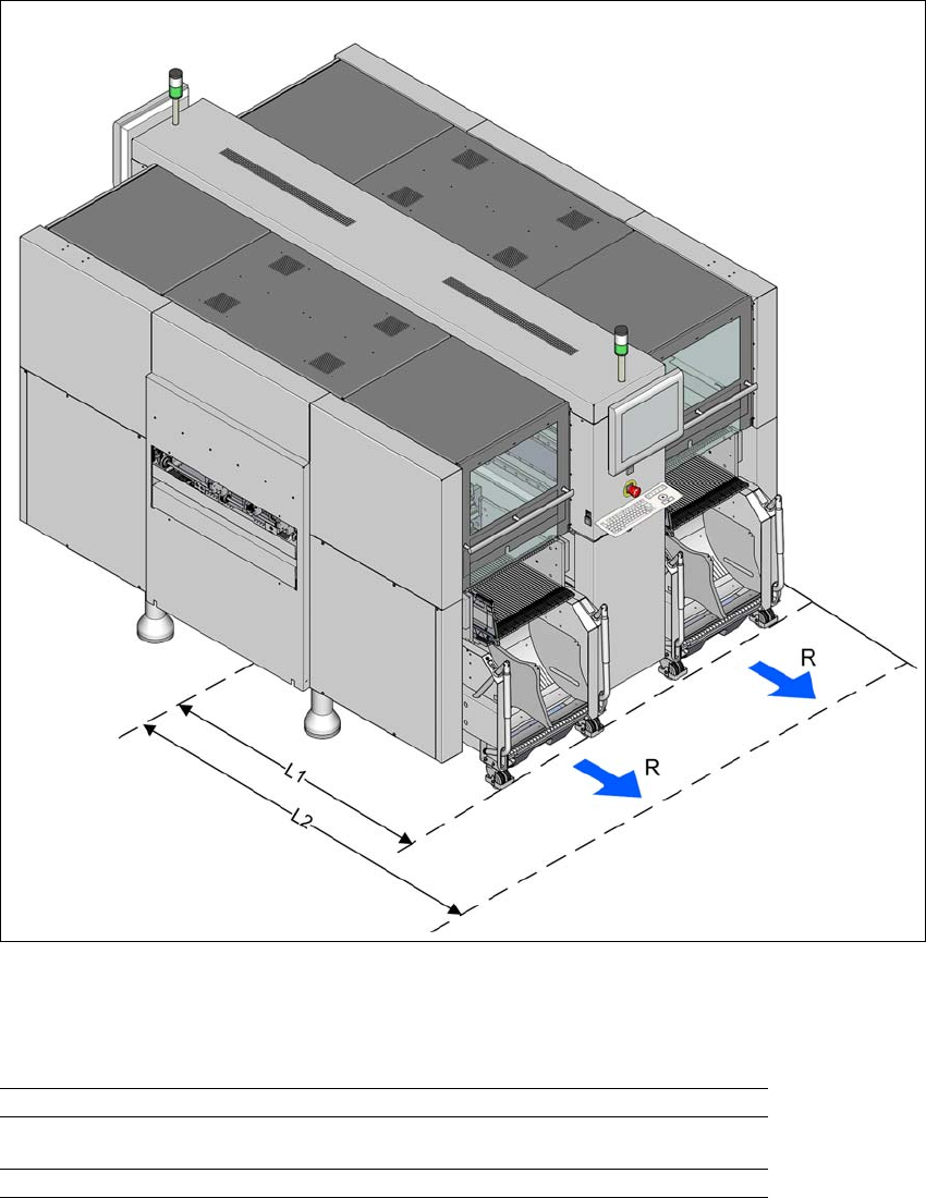
3.3.4 Maneuvering radii for the component trolleys in SX4 machines
3
Fig. 3.3 - 4 Maneuvering radii for the component trolleys in SX4 machines
The maneuvering radii "R" for the component trolleys in SX4 machines is:
3
Maneuvering radius R 600 mm
Distance L1: Machine center to outer edge of X component
trolley
1257.50 mm
Distance L2: Machine center to wall 1857.50 mm
3 Technical data and assemblies User Manual SIPLACE SX4/DX4
3.3 Dimensions and weight From software version SC.706.xx Version 06/2012 EN
108
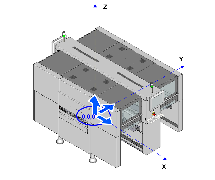
3.3.5 Center of gravity
3
Fig. 3.3 - 5 Center of gravity in millimeters (example of SX4)
X coordinate 0 mm
Y coordinate 0 mm
Z coordinate 630 mm
These center of gravity coordinates relate to placement machines with a PCB conveyor height of
900 mm.