00196693-03_UM_SX4DX4_SR706_EN.pdf - 第16页
1 Introduction User Manual SIPLACE SX4/DX4 1.1 SIPLACE SX4 From software version SC.706.xx Version 06/2012 EN 16 1.1 SIPLACE SX4 1 Fig. 1.1 - 1 SIPLACE SX4 placement machine The SIPLACE SX4 placement machine has the foll…

User Manual SIPLACE SX4/DX4 1 Introduction
From software version SC.706.xx Version 06/2012 EN
15
1 Introduction
This operating guide is a manual or reference work for operating and setting up the SIPLACE
®
SX4 and DX4 placement machines. This document is the original operating guide.
PLEASE NOTE: 1
– The placement machines SX4 and DX4 are in principle of identical design - any deviations
from this will be explicitly indicated.
– For the relevant configurations and other options, refer to the individual specifications for the
SIPLACE SX4 or SIPLACE DX4 machines.
– The diagrams in this user manual show the SIPLACE SX4 as a rule. These diagrams are also
applicable in principle for the SIPLACE DX4. However, a separate diagram of the DX4 will be
shown where necessary.
1
The header of each chapter contains the release and software version, to which this manual ap-
plies.
1 Introduction User Manual SIPLACE SX4/DX4
1.1 SIPLACE SX4 From software version SC.706.xx Version 06/2012 EN
16
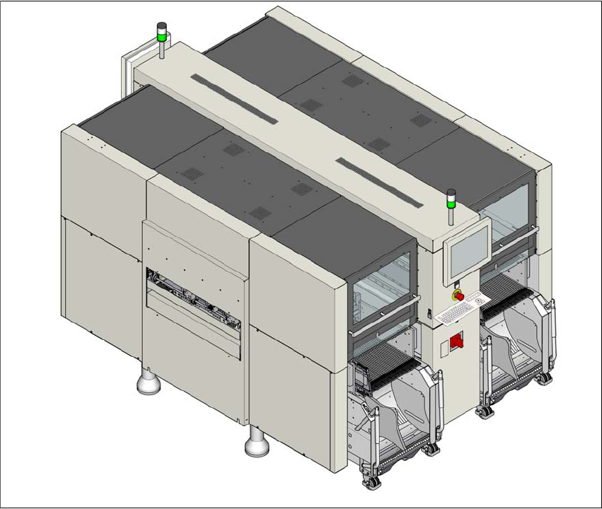
1.1 SIPLACE SX4
1
Fig. 1.1 - 1 SIPLACE SX4 placement machine
The SIPLACE SX4 placement machine has the following distinguishing features:
– High precision,
– High configuration flexibility,
– Head and gantry modularity
– Placement performance up to the high end process range and
– A wide ranging component spectrum from 01005 components to a size of
110 mm x 10 mm.

User Manual SIPLACE SX4/DX4 1 Introduction
From software version SC.706.xx Version 06/2012 EN 1.1 SIPLACE SX4
17
Three placement methods are possible for processing the components:
– Collect&Place,
– Pick&Place and
– A combination of Collect&Place and Pick&Place (mixed mode).
The SIPLACE SX4 placement machine has four gantries. The head modularity principle devel-
oped by SIPLACE allows you to change placement heads quickly and easily. For an overview of
the placement head configuration, refer to section 1.1.1
from page 17.
These can be quickly and accurately positioned by linear motors, moving independently of one
another in the X and Y directions.
There are four locations available for supplying components. These can be fitted with component
trolleys and configured with up to 40 tracks.
1.1.1 Overview of placement head configuration
1
CPP_H = Multistar CPP in high assembly position
Placement area 1 Placement area 2
C&P20 / C&P20 C&P20 / C&P20
C&P20 / C&P20 CPP / CPP
C&P20 / C&P20 TH / TH
C&P20 / C&P20 CPP_H/TH
CPP / CPP CPP / CPP
CPP / CPP CPP_H/TH
CPP / CPP TH / TH