00196693-03_UM_SX4DX4_SR706_EN.pdf - 第214页
4 Setting up and commissioning User Manual SIPLACE SX4/DX4 4.3 Setting up the machine From software version SC.706.xx Version 06/2012 EN 214 4 Fig. 4.3 - 4 Machine feet (example of SX4) 4 (1) Outer machine foo t, 4 x, 2 …
User Manual SIPLACE SX4/DX4 4 Setting up and commissioning
From software version SC.706.xx Version 06/2012 EN 4.3 Setting up the machine
213
Make sure that the forks are evenly loaded when you lift the machine. A firm support between
the forks and machine will prevent the machine tilting when it is raised. This will also prevent
a one-sided load on the machine feet, which would deform the fixing of the machine feet. We
recommend that a second person watch the machine as it is raised, and make sure that the
machine does not tip to one side when lifted with the fork-lift.
With the fork-lift, raise the machine approximately 35 cm. This prevents the risk of any injuries
to your feet if the machine feet are unintentionally lowered.
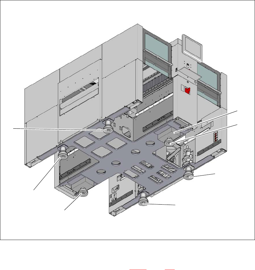
The machine stands on 6 feet.
– 4 outer machine feet (item 1 in fig. 4.3 - 4
, page 214 )
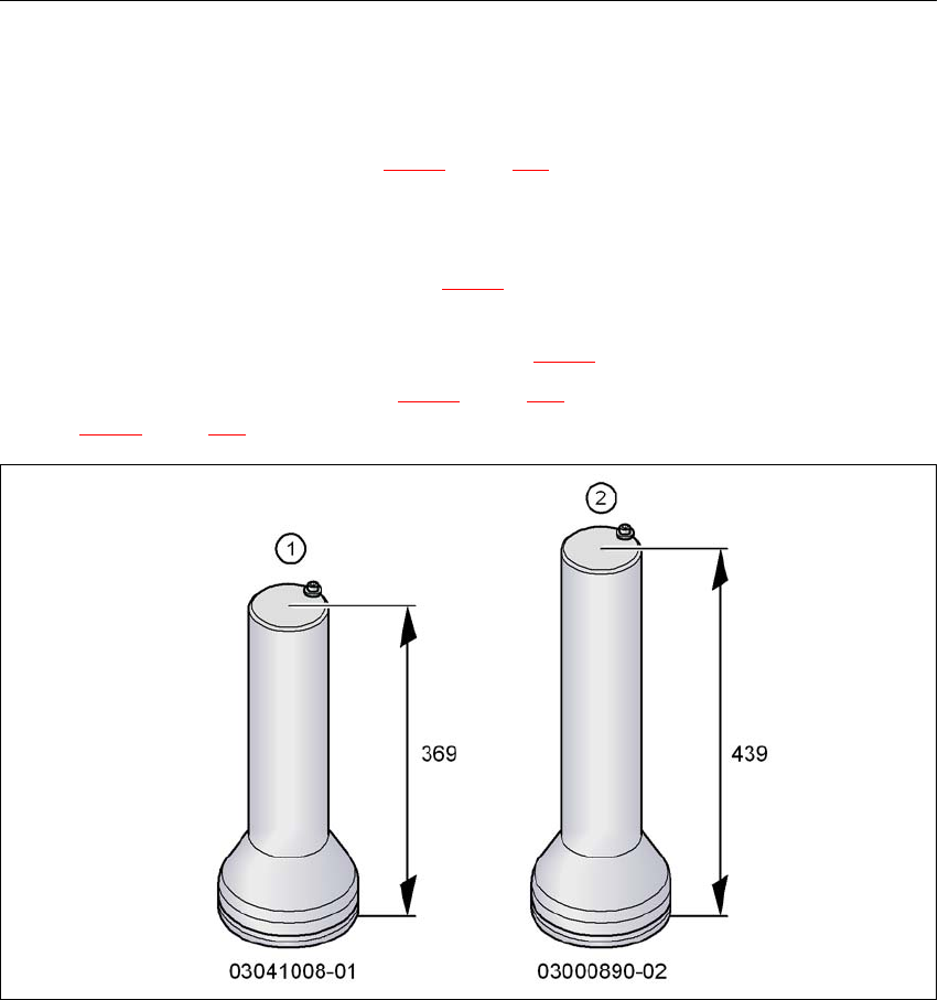
There are two versions of the outer machine feet: 4
– Outer machine feet for the PCB conveyor height 830 mm, length 369 mm,
Item no. 03041008-01 (item 1 in fig. 4.3 - 3
)
– Outer machine feet for the PCB conveyor heights 900,930 and 950 mm, length
439 mm, Item no. 03000890-02 (item 2 in fig. 4.3 - 3
).
– 2 middle machine feet (item 2 in fig. 4.3 - 4
, page 214) with 2 spacers (item 3 and item 4 in
fig. 4.3 - 4
, page 214) for height adjustment, where necessary.
4
Fig. 4.3 - 3 Outer machine feet - two versions (dimensions in millimeters)
4 Setting up and commissioning User Manual SIPLACE SX4/DX4
4.3 Setting up the machine From software version SC.706.xx Version 06/2012 EN
214
4
Fig. 4.3 - 4 Machine feet (example of SX4)
4
(1) Outer machine foot, 4 x, 2 versions (see fig. 4.3 - 3, page 213 )
(2) Middle machine foot, 2 x
(3) Spacer on the side of the power supply unit
(2)
(2)
(1)
(1)
(1)
(1)
(3)
User Manual SIPLACE SX4/DX4 4 Setting up and commissioning
From software version SC.706.xx Version 06/2012 EN 4.3 Setting up the machine
215
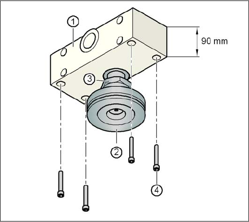
4.3.6.1 Presetting the height of the middle machine feet
The middle machine feet are preset first of all. The spacer must be screwed to the correct position
on the underside of the machine: this will vary according to the height of the machine.
Setting a board conveyor height of 830 mm 4
You do not need a spacer for a board conveyor height of 830 mm.
Screw the middle machine foot as far as possible into the threaded hole provided.
Setting a board conveyor height of 900 mm 4
You do need a spacer for a board conveyor height of 900 mm.
Make sure that the 90 mm side of the spacer is vertically aligned and the hole for the middle
machine foot indicates downwards.
4
4
4
4
4
4
4
4
4
4
4
4
Fig. 4.3 - 5 Aligning the spacer for a conveyor height of 900 mm
4
(1) Spacer height of 90 mm
(2) Middle machine foot
(3) Lock nut M24
(4) Hexagon socket head screw M12x80, 4x