00196693-03_UM_SX4DX4_SR706_EN.pdf - 第201页
User Manual SIPLACE SX4/DX4 4 Setting up and commissioning From software version SC.706.xx V ersion 06/2012 EN 4.2 Infrastructure at the installation location 201 4.2.3.2 Checking the main power supply Check whether the …
4 Setting up and commissioning User Manual SIPLACE SX4/DX4
4.2 Infrastructure at the installation location From software version SC.706.xx Version 06/2012 EN
200
4.2.3 Main power supply
4
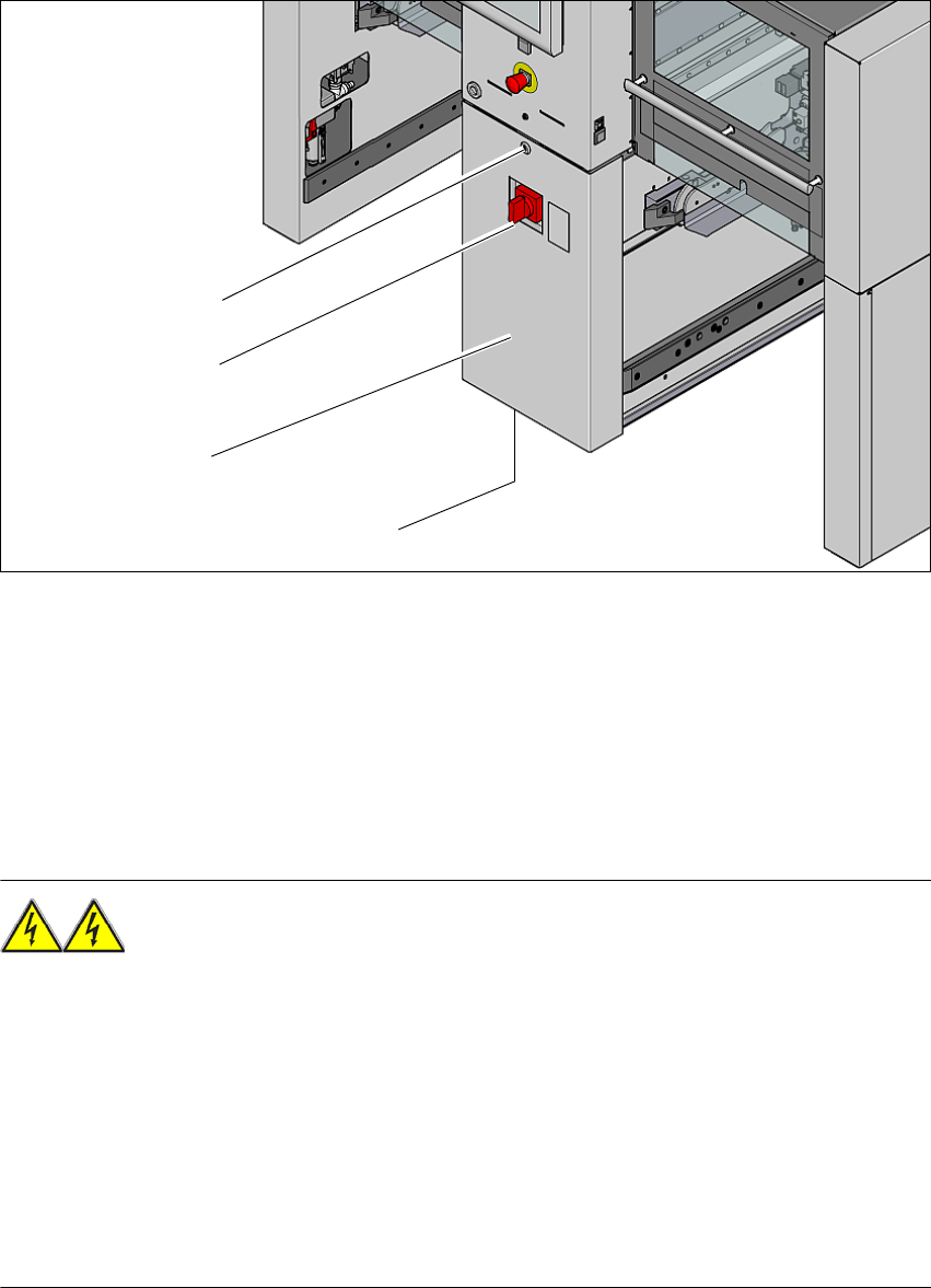
Fig. 4.2 - 2 Position of the power supply on the machine (example of SX4)
(1) Lock
(2) Main power switch secured to prevent switching on again
(3) Power supply unit (behind the cover)
(4) Mains connection cable
4.2.3.1 Danger notes
WARNING
The machine is supplied with 3 x 200 V~, 3 x 208 V~, 3 x 220 V~, 3 x 230 V~, 3 x 380 V~,
3x400V~ or 3x415V~ ± 5%, 50/60Hz mains voltage. This means that some parts of the sys-
tem carry potentially lethal voltages - even when switched off at the main power switch. Incorrect
handling of the machine can therefore result in death or severe injury or considerable damage to
equipment. 4
Always follow the applicable accident prevention and DIN regulations (particularly EN 60204,
part 1 or IEC 60204, part 1) and the applicable regulations in your own country.
Only trained and qualified personnel may remove the cover over the power supply unit and
connect the machine to the power supply.
(1)
(2)
(3)
(4)
User Manual SIPLACE SX4/DX4 4 Setting up and commissioning
From software version SC.706.xx Version 06/2012 EN 4.2 Infrastructure at the installation location
201
4.2.3.2 Checking the main power supply
Check whether the power supply complies with the prescribed machine specifications (see table
in section 3.2
, page 101).
PLEASE NOTE: 4
The documentation "Network Configuration (Electrics and Compressed Air) for SMD Machines at
Customer Site", Item No. 00191409-xx includes the measures required to achieve the specifica-
tions needed.
PLEASE NOTE: 4
For technical reasons, load peaks occur in the power supply. Please contact your power com-
pany to clarify the mains impedance, if necessary.
4.2.3.3 Power supply cable - specification
The following specifications apply at the customer end to the power supply for the machine:
– 5 x 2.5 mm² at 3 x 380 V~ / 3 x 400 V~ / 3 x 415 V~ at cable lengths of up to 20 meters be-
tween placement machine distribution and mains connection at the customer end. Over 20
meters cable 5 x 4 mm².
– 5 x 4 mm² at 3 x 200 V~/ 3 x 208 V~ / 3 x 220 V~ / 3 x 230 V~ at cable lengths of up to 20
meters between placement machine distribution and mains connection at the customer end.
Over 10 meters cable 5 x 6 mm².
The color coding for the wires will depend on the country in which the system is operated.
WARNING 4
The electrical leads to each individual machine and to the options installed must be clearly
labeled and easily assignable. The regulations of the country in which the machine is operated
apply.
4 Setting up and commissioning User Manual SIPLACE SX4/DX4
4.2 Infrastructure at the installation location From software version SC.706.xx Version 06/2012 EN
202
4.2.3.4 Mains connection - delivery configuration
The main power connection is configured according to the power supply of the country concerned.
– The machine is configured for voltages of 204V AC, 220V AC or 230V AC.
The machine has a mains power cable WITHOUT plug. 4
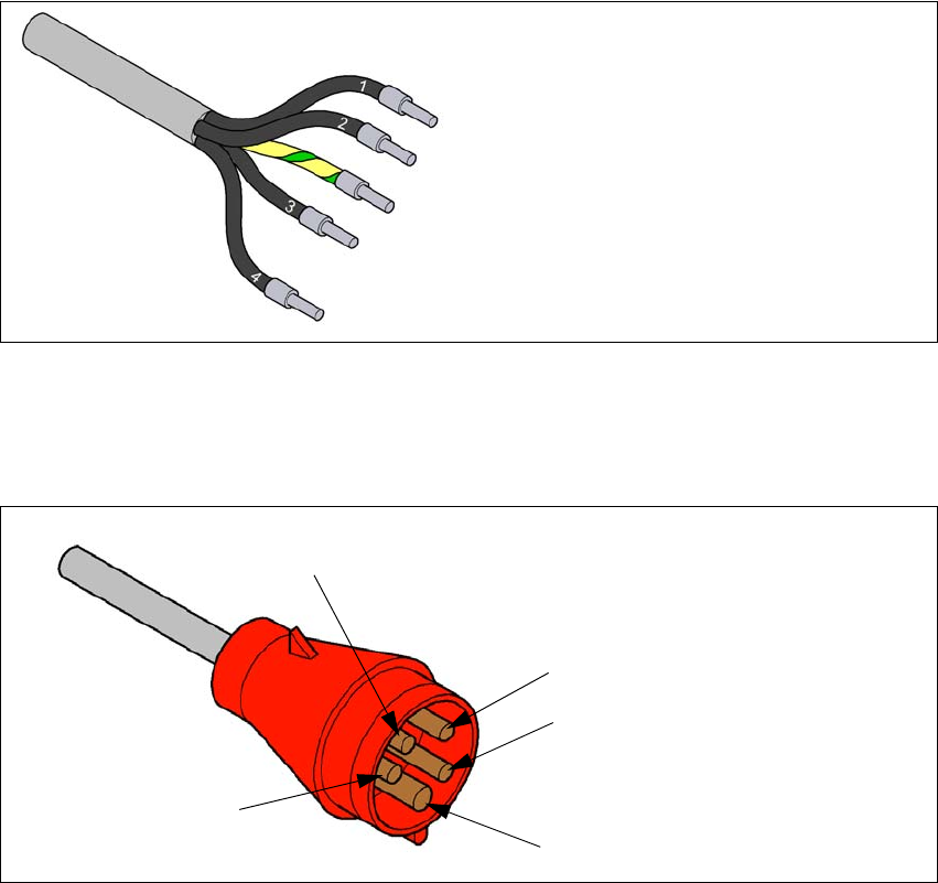
4
Fig. 4.2 - 3 Description of wires in the mains power cable
– The machine is configured for voltages of 380V AC, 400V AC or 415V AC.
The machine has a mains power cable WITH Cekon plug. 4
4
Fig. 4.2 - 4 Assignment in the Cekon plug
1 = (L1): three-phase
2 = (L2): three-phase
3 = (L3): three-phase
4 = (N): neutral conductor
green/yellow = (PE): conductor
PE
L1
L2
L3
N