00196693-03_UM_SX4DX4_SR706_EN.pdf - 第311页
User Manual SIPLACE SX4/DX4 6 Station extensions From software version SC.706.xx V ersion 06/2012 EN 6.1 Nozzle changer 311 6.1.3.3 Position of nozzle changer fo r the T winSt ar One nozzle changer can be installe d at e…
6 Station extensions User Manual SIPLACE SX4/DX4
6.1 Nozzle changer From software version SC.706.xx Version 06/2012 EN
310
6.1.3 Nozzle changers for the SIPLACE TwinStar (SX4 only)
Item no. 03005191-xx Magazine for 2 nozzles
Item no. 03001807-xx Magazine for 1 nozzle
6
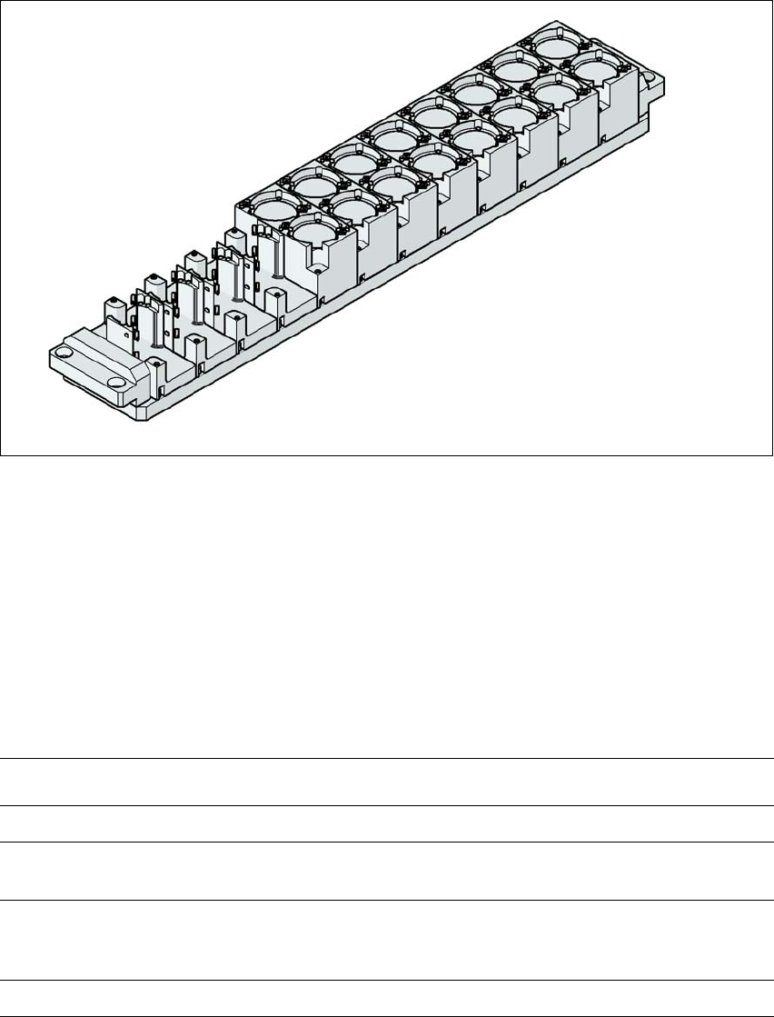
Fig. 6.1 - 13 Nozzle changer for the SIPLACE TwinStar
6.1.3.1 Description
This nozzle changer can accommodate up to 12 nozzle magazines. There are two different mag-
azine types available: standard magazines and magazines for special nozzles or grippers. The
magazines are seated on a common support. They are centered with two parallel pins and fixed
in place with two countersunk screws.
6.1.3.2 Technical data
6
Nozzle changer for the SIPLACE TwinStar
Dimensions (length x width x height) 448 mm x 68.5 mm x 49 mm
Number of nozzle holders 16 for standard nozzles
4 for special nozzles or grippers
Nozzle types 5xx, standard
4 xx with adapter
9 xx with adapter
Nozzle changeover time Approx. 2 s per nozzle
User Manual SIPLACE SX4/DX4 6 Station extensions
From software version SC.706.xx Version 06/2012 EN 6.1 Nozzle changer
311
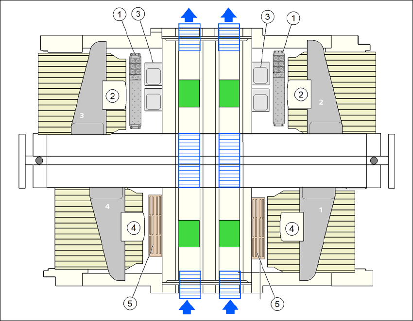
6.1.3.3 Position of nozzle changer for the TwinStar
One nozzle changer can be installed at each of the following locations for the TwinStar.
Nozzle changer at location 1, 3 and 4: 12 magazines
Nozzle changer at location 2: 10 magazines
This gives a total capacity of 2 nozzle changers with 22 magazines and a total of 44 nozzle ga-
rages.
6
Fig. 6.1 - 14 Position of nozzle changer for the TwinStar - configuration example
(1) Nozzle changer for the TwinStar
(2) TwinStar
(3) Stationary cameras
(4) MultiStar
(5) Nozzle changer for the MultiStar
6 Station extensions User Manual SIPLACE SX4/DX4
6.1 Nozzle changer From software version SC.706.xx Version 06/2012 EN
312
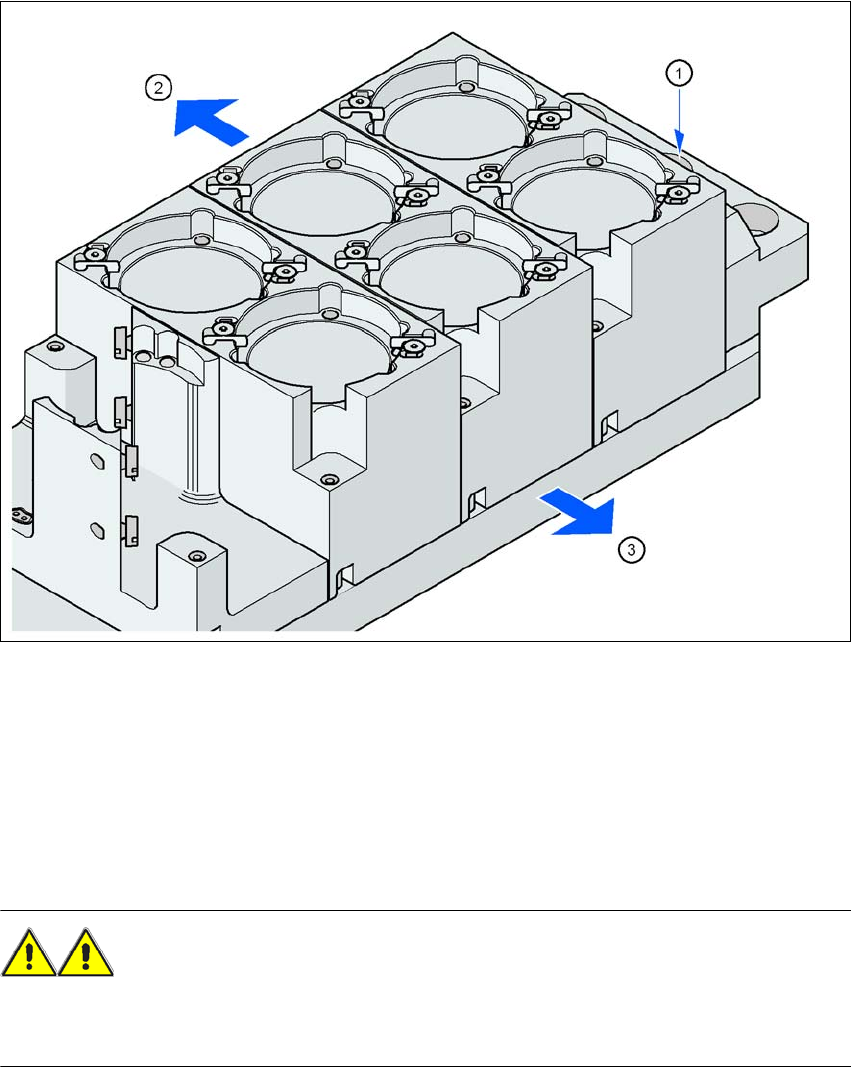
6.1.3.4 Assembly
The nozzle changer is fixed to the component trolley docking unit.
6
Fig. 6.1 - 15 Assembly position
(1) Marking hole
(2) Operator side
(3) Arrow pointing toward the PCB conveyor
6
Align the nozzle changer so that the marking hole (item 1) is on the left, as viewed by the op-
erator.
WARNING 6
– Only install the corresponding nozzle changers for each placement head. There is a risk of
head crashes with mixed configurations.