00196693-03_UM_SX4DX4_SR706_EN.pdf - 第85页
User Manual SIPLACE SX4/DX4 2 Operational safety From software version SC.706.xx V ersion 06/2012 EN 2.10 Energy state of the machine after switching off at the main power switch 85 2.10.1 Machine switched off at the mai…
2 Operational safety User Manual SIPLACE SX4/DX4
2.10 Energy state of the machine after switching off at the main power switch From software version SC.706.xx Version 06/2012 EN
84
2.10 Energy state of the machine after switching off at the
main power switch
2
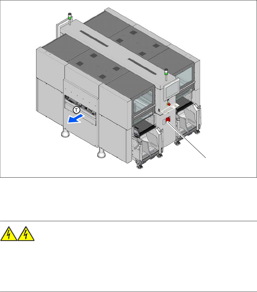
Fig. 2.10 - 1 Position of the power supply on the machine (example of SX4)
2
WARNING
The machine is supplied with 3 x 200 V~, 3 x 208 V~, 3 x 220 V~, 3 x 230 V~, 3 x 380 V~,
3x400V~ or 3x415V~ ± 5%, 50/60Hz mains voltage. This means that some parts of the sys-
tem carry potentially lethal voltages - even when switched off at the main power switch. Incorrect
handling of the machine can therefore result in death or severe injury or considerable damage to
equipment. 2
Always follow the applicable accident prevention and DIN regulations (particularly EN 60204,
part 1 or IEC 60204, part 1) and the applicable regulations in your own country.
The guard over the power supply unit must ONLY be opened by appropriately qualified and
trained personnel.
(1) Main power switch
(1)
User Manual SIPLACE SX4/DX4 2 Operational safety
From software version SC.706.xx Version 06/2012 EN 2.10 Energy state of the machine after switching off at the main power switch
85
2.10.1 Machine switched off at the main switch, but still connected
WARNING
The following components still carry potentially lethal voltages even if the main power switch is
switched off:
– Mains connection terminals in the transformer unit L1, L2 and L3 of main switch.
– Service socket X102 with F1 automatic circuit breaker switched on.
– The color of all individual wires, which still carry potentially lethal voltages even if the main
power switch is switched off, is brown.
2
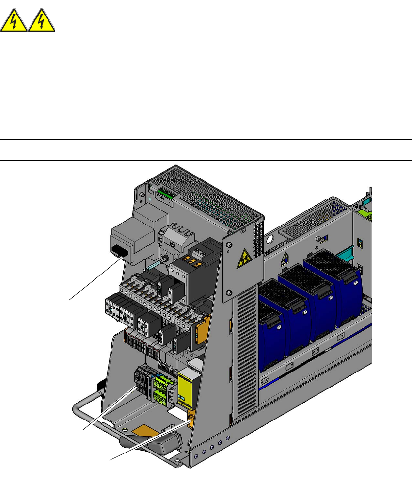
Fig. 2.10 - 2 Power supply unit, front view
(1) Service socket (X102)
(2) Mains connection terminals (X100)
(3) Main switch (Q1)
(3)
(1)
(2)
2 Operational safety User Manual SIPLACE SX4/DX4
2.10 Energy state of the machine after switching off at the main power switch From software version SC.706.xx Version 06/2012 EN
86
2
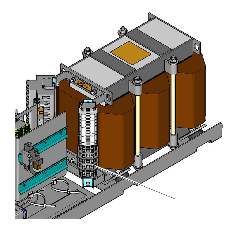
Fig. 2.10 - 3 Power supply unit, side view
(1) Primary connection terminals on the transformer for connection of country-specific mains
voltages.
The following table specifies the voltages of modules when the machine is switched off at the main
switch, but still connected to the mains supply.
(1)