00196693-03_UM_SX4DX4_SR706_EN.pdf - 第129页
User Manual SIPLACE SX4/DX4 3 Technical data and assemblies From software version SC.706.xx Version 06/2012 EN 3.6 Gantry system 129 3.6 Gantry system 3.6.1 Position of the gantries 3 Fig. 3.6 - 1 Position of the gantrie…

3 Technical data and assemblies User Manual SIPLACE SX4/DX4
3.5 Placement head From software version SC.706.xx Version 06/2012 EN
128
Component specification
b
max. height
min. lead pitch
min. lead width
min. ball pitch
min. ball diameter
min. dimensions
max. dimensions
max. weight
c
25 mm (higher available on request)
0.3 mm
0.15 mm
0.35 mm
0.2 mm
1.0 mm x 0.5 mm
55 mm x 45 mm (single measure-
ment)
For use with two nozzles
50 mm x 50 mm or
69 mm x 10 mm
For use with one nozzle
78 mm x 78 mm or
110 mm x 10 mm
up to 200 mm x 110 mm (with
restrictions)
100 g
25 mm (higher available on request)
0.25 mm
0.1 mm
0.14 mm
0.08 mm
0.6 mm x 0.3 mm
16 mm x 16 mm (single measure-
ment)
55 mm x 55 mm (multiple measure-
ment)
100 g
Programmable set-down
force
1.0 N - 15 N
2.0 N - 30 N
d
1.0 N - 15 N
2.0 N - 30 N
d
Nozzle types
e
5 xx (standard)
4 xx + adapter
8 xx + adapter
9 xx + adapter
gripper
5 xx (standard)
4 xx + adapter
8 xx + adapter
9 xx + adapter
gripper
Nozzle spacing for the two
Pick&Place heads
70.8 mm 70.8 mm
X/Y accuracy
f
± 26 μm / 3, ± 35 μm / 4 ± 22 μm / 3, ± 30 μm / 4
Angular accuracy ± 0.05° / 3, ± 0.07° / 4 ± 0.05° / 3, ± 0.07° / 4
Component camera type 33 25
Illumination level 6 6
Possible illumination level
settings
256
6
256
6
a) Please note that the component range that can be placed is also affected by the pad geometry, the custom-
er-specific standards and the packaging tolerances.
b) If the C&P head and TwinStar are combined in the same placement area, the maximum dimensions may be
restricted.
c) If standard nozzles are used
d) SIPLACE high force head, section 6.7
, page 331.
e) Over 300 different nozzles and 100 gripper types available, extensive nozzle database available online.
f) The accuracy value, measured using the vendor-neutral IPC standard.
User Manual SIPLACE SX4/DX4 3 Technical data and assemblies
From software version SC.706.xx Version 06/2012 EN 3.6 Gantry system
129
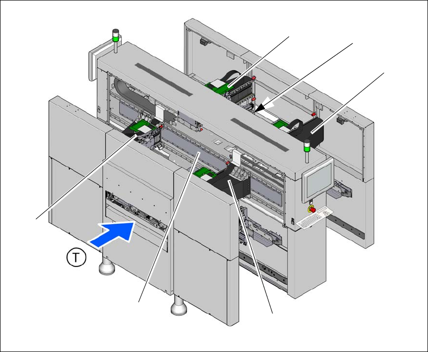
3.6 Gantry system
3.6.1 Position of the gantries
3
Fig. 3.6 - 1 Position of the gantries (example of SX4)
(1) Y axis, gantry 1 and gantry 4
(2) X axis, gantry 1
(3) X axis, gantry 2
(4) Y axis, gantry 3 and gantry 4 (concealed)
(5) X axis, gantry 3
(6) X axis, gantry 4
(T) Direction of PCB transport
(1)
(3)
(6)
(4)
(2)
(5)
3 Technical data and assemblies User Manual SIPLACE SX4/DX4
3.6 Gantry system From software version SC.706.xx Version 06/2012 EN
130
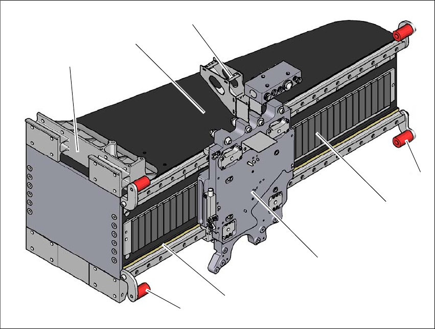
3.6.2 Structure of the X axis
3
Fig. 3.6 - 2 Design of X axis - view of head mount
(1) Head mount with X-axis linear motor (primary part)
(2) Y linear motor with fixed bearing (primary part)
(3) Guidance system with permanent magnet (secondary part of the X linear motor)
(4) End position bumper (4x)
(5) Head board mount
(6) Gantry arm
(7) Length measurement system
The gantry arm is made of a carbon fiber composite. This technology allows assemblies to be
made with extremely low weight and high rigidity.
The X axis is driven by a linear motor. The secondary part of the drive consists of a permanent
magnet and is mounted on the gantry arm. The primary part is bolted to the head mount. The head
mount has been designed so that all placement head types can be accommodated - one of the
benefits of the great flexibility in the SIPLACE machines.
(4)
(3)
(1)
(5)
(2)
(6)
(4)
(7)