00196693-03_UM_SX4DX4_SR706_EN.pdf - 第305页
User Manual SIPLACE SX4/DX4 6 Station extensions From software version SC.706.xx V ersion 06/2012 EN 6.1 Nozzle changer 305 6.1.2.3 Position of nozzle changer for th e SIPLACE MultiSt ar Locations 1, 2, 3 and 4 can each …
6 Station extensions User Manual SIPLACE SX4/DX4
6.1 Nozzle changer From software version SC.706.xx Version 06/2012 EN
304
Nozzle magazine for 28xx nozzles 6
6
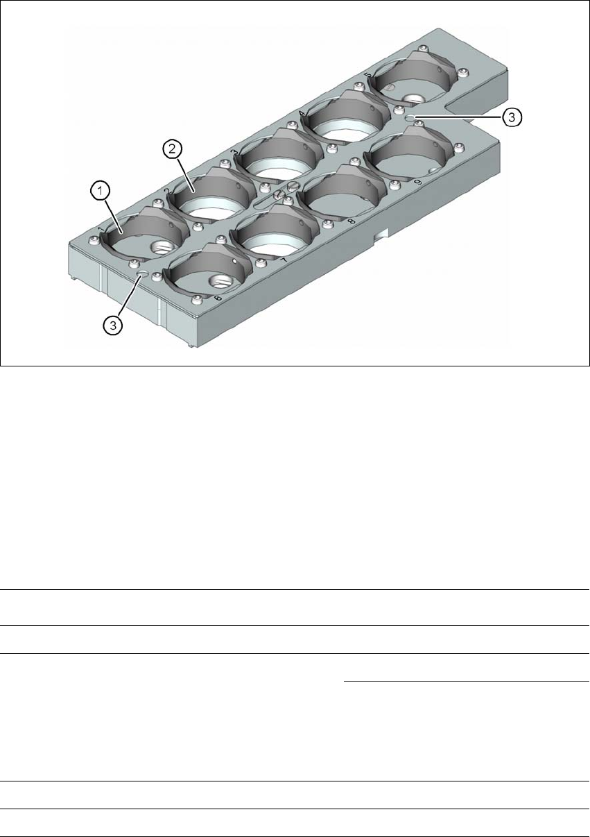
Fig. 6.1 - 8 Nozzle magazine for 28xx nozzles
(1) 5 garages for 28xx nozzles with a maximum nozzle length of 12.5 mm
(garage numbers 1, 5, 6, 8 and 9)
(2) 4 garages for 28xx nozzles with a maximum nozzle length of 16.5 mm
(garage numbers 2, 3, , 4 and 7)
(3) Fiducials (only visible when locking plate open)
6.1.2.2 Technical data
6
6
Nozzle changer for the SIPLACE MultiStar
Dimensions (length x width x height) 449 mm x 62.7 mm x 77.7 mm
Number of nozzle holders
Type 20xx 60
Type 28xx 9
Nozzle types 20xx (CPP head)
28xx (CPP head)
Nozzle changeover time approx. 2s per nozzle
Compressed air connection 0.48 MPa (4.8 bar)
User Manual SIPLACE SX4/DX4 6 Station extensions
From software version SC.706.xx Version 06/2012 EN 6.1 Nozzle changer
305
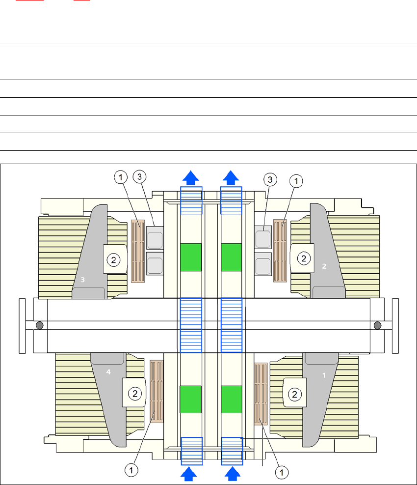
6.1.2.3 Position of nozzle changer for the SIPLACE MultiStar
Locations 1, 2, 3 and 4 can each accommodate one nozzle changer for the CPP head (item 1 in
fig. 6.1 - 9
, page 305).
This gives the following nozzle changer configurations for the placement machine:
6
6
Fig. 6.1 - 9 Position of nozzle changer for the SIPLACE MultiStar - configuration example
6
Location Number of nozzle
magazines
Number of spare nozzle
magazines
Number of nozzle
holders
1 5 x 20xx + 1 x 28xx - 60 x 20xx, 9 x 28xx
2 4 x 20xx 2 48 x 20xx
3 5 x 20xx + 1 x 28xx - 60 x 20xx, 9 x 28xx
4 4 x 20xx 2 48 x 20xx
(1) Nozzle changer
(2) SIPLACE MultiStar
(3) Stationary cameras
6 Station extensions User Manual SIPLACE SX4/DX4
6.1 Nozzle changer From software version SC.706.xx Version 06/2012 EN
306
PLEASE NOTE: 6
– The placement heads at locations 2 and 4 are not able to access the two innermost nozzle
magazines (item 2 in fig. 6.1 - 9
).
– All magazine locations must be filled since the safety circuit stops the machine in response
to missing magazines or magazines that are not seated correctly.
6.1.2.4 Assembly
The nozzle changers are fixed to the component trolley docking unit.
6
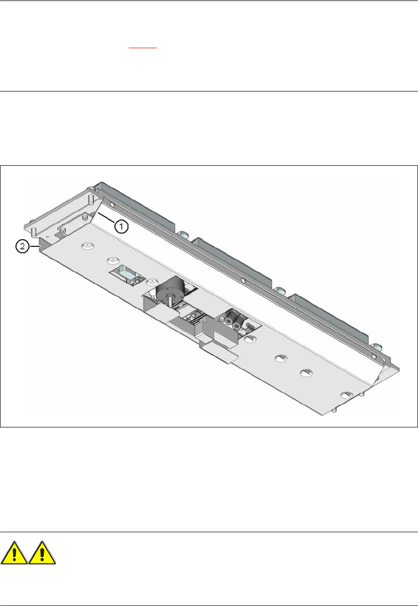
Fig. 6.1 - 10 Assembly position of nozzle changer - view from below
(1) Sloping side points towards the component trolley docking unit
(2) Vertical side points towards the PCB conveyor
Align the nozzle changer so that the sloping side points towards the component trolley dock-
ing unit.
WARNING 6
– Only install the corresponding nozzle changers for each placement head. There is a risk of
head crashes with mixed configurations.